At a glance
| Patent number | CN118058647B (application CN202410497277) |
| Type | China invention patent (发明专利) - protects product shape, structure, and method |
| Original title | Dehairing Brush Head and Method for Household Dust Collector (一种家用吸尘器的除毛刷头及除毛方法) |
| Patent owner | Suzhou Aza Clean Electric Technology Co ltd |
| Inventors | Liu Fujian, Wang Lailai |
| Filing date | 2024-04-24 |
| Grant date | 2024-07-02 |
| Status (China) | In force - valid until at most 2044-04-24, provided annual fees are paid |
| Patent family | Chinese filings only - no US, European, Japanese, PCT or other filings listed |
| Cited by | 0 later documents |
| Source | Google Patents (search for CN118058647B) |
What the claims cover, in plain language
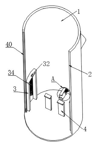
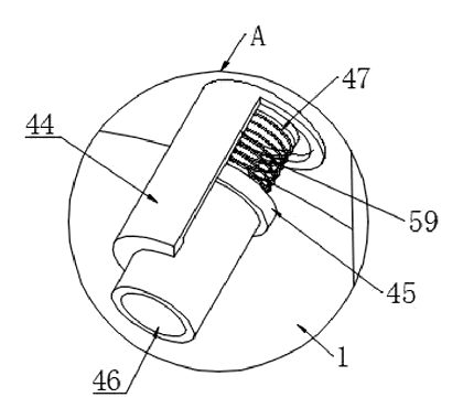
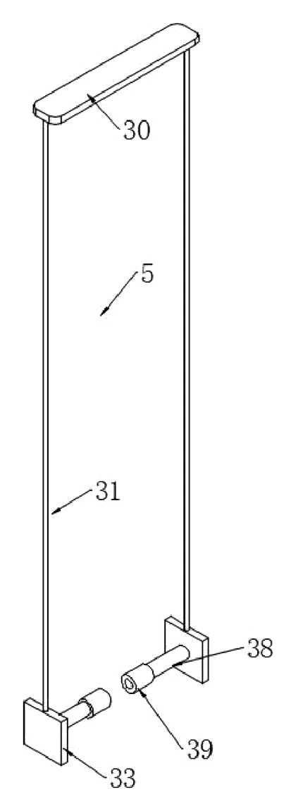
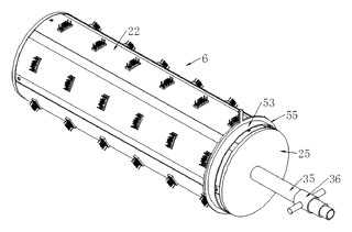
Claim 1 defines a brush head comprising a containing shell that attaches to a vacuum exhaust pipe. Inside, an avoidance groove and guide frames support a lifting piece. This lifting piece holds a rolling piece (the roller) and meshes with a toothed plate via a gear ring, allowing the roller to rotate and change orientation. The roller contains multiple fixed boxes with sliding dehairing parts. These parts include bristles and adhesive strips mounted on plates that slide within the boxes. Vent holes and sliding pipes connect the interior of the roller to the air stream, enabling negative pressure to drive the movement of the dehairing parts. An annular scraping piece is included to wipe hair off the roller.
Claims 2-7 add specific details: hook-and-loop fasteners for the adhesive strips, limit holes for the lifting rods, an annular cavity with arc springs for resetting the side plate, and an electromagnetic coil system with a piston ring to automate the air valve opening/closing. Claim 7 specifically describes the sliding guide grooves for the scraper.
Claim 8 outlines the method of use, detailing the sequence of rotating the side plate, pushing the pressing plate to deploy the roller, cleaning via friction/static, and then using the vacuum’s suction/exhaust to retract the bristles and scrape the hair away.
This is a simplified reading for orientation only. The legal scope is defined by the exact claim wording in the official Chinese document.
What this means for US production
This patent was filed only in China and is currently in force. Making or selling this specific design in China requires the owner’s permission. However, since there are no US patents claiming priority from this application, the design itself is not protected in the United States.
Two points to settle early:
- Other patents may exist. Vacuum cleaner attachments, particularly those involving self-cleaning rollers or anti-tangle technology, are a crowded field with numerous active US patents held by major appliance manufacturers (e.g., Dyson, SharkNinja, iRobot). A freedom-to-operate (FTO) review is essential to ensure your implementation does not infringe on existing US utility patents regarding similar mechanical retraction or air-assisted cleaning methods.
- Component Sourcing. The mechanism relies on precise interaction between gears, springs, and air channels. Ensure that any proprietary components from the original Chinese manufacturer are not required for basic functionality, as you may need to redesign interfaces to avoid direct copying of the patented assembly layout.
Customization and manufacturing
What can be customized
| Area | Options |
|---|---|
| Mounting Interface | Thread sizes and shapes to fit different vacuum brands (Dyson, Shark, generic universal adapters). |
| Bristle Material | Nylon, silicone, or natural fibers depending on surface type (hardwood vs. carpet). |
| Adhesive Strip Type | Replaceable velcro-style pads vs. integrated sticky sheets; material grade for durability. |
| Control System | Manual lever (basic claims) vs. Electromagnetic/Smart version (claims 6-7) requiring battery integration. |
| Color and Finish | Plastic resin colors, matte or glossy textures, branding decals. |
Things to plan for (US market)
- UL 507 / IEC 60335 - If the device includes an electric motor or battery pack (as per Claim 6), it must meet safety standards for household electrical appliances.
- CPSC Safety Guidelines - For products intended for homes with children/pets, ensure small parts do not detach easily to prevent choking hazards.
- RoHS Compliance - Restriction of hazardous substances in electronic components (coils, controllers, batteries).
- California Prop 65 - Screening of plastics and adhesives for carcinogenic materials.
How a project runs
- Inquiry - Define compatibility requirements (which vacuums?) and desired features (manual vs. auto).
- Design - CAD modeling of the gear ratio, spring rates, and air channel dimensions.
- Prototype - 3D print functional samples to test the retraction mechanism and hair clearance efficiency.
- Pilot Run - Small batch injection molding for critical plastic parts; assemble and test durability cycles.
- Production - Full-scale tooling, assembly line setup, quality control testing.
Quantities & timeline
The complexity lies in the multi-part sliding assemblies and the precision required for the gear meshing to ensure smooth rotation. Tooling costs will be driven by the number of cavities needed for the small fixed boxes and sealing covers. Certification tests for electrical safety (if applicable) add lead time. Send us your target vacuum models, quantity estimates, and preferred feature set and we will reply with options.
Production notes
Tooling and process
Injection molding is likely the primary process for the containing shell, fixed boxes, and sliding pipes. Complex geometries like the avoidance groove and internal guides may require undercuts or side-actions in the mold. Stamping could be used for metal gears or shafts if durability demands exceed plastic capabilities.
Cost drivers
Part count is typically high due to the individual sliding units for each bristle cluster. Molding small, intricate parts increases cycle times and mold complexity. If the electromagnetic option is chosen, battery pack assembly and microcontroller sourcing will significantly raise unit costs compared to the purely mechanical version.
Prototyping path
Prototyping typically starts with a 3D model and interference check to validate the gear meshing and slider movements. Print the body and lifting pieces to assess fit. CNC machine the stressed parts like the shafts or gears for initial functional testing before committing to steel molds.
What we would change before tooling
Verify the seal integrity between the sliding pipes and fixed boxes; leaks here would negate the negative pressure effect. Adjust spring rates to ensure the lifting piece returns fully without binding. Test the adhesive strip removal force to balance cleaning efficacy with ease of replacement.
Common failure points
Thin walls on the sliding pipes may warp or sink during molding, causing jams. Seal leaks after repeated use will reduce suction power. Spring fatigue could prevent the mechanism from resetting properly. Trapped hair residue in crevices might eventually block the sliding paths despite the self-cleaning intent.
Patent drawings
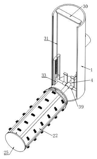
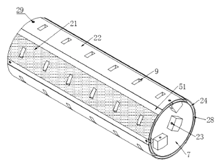
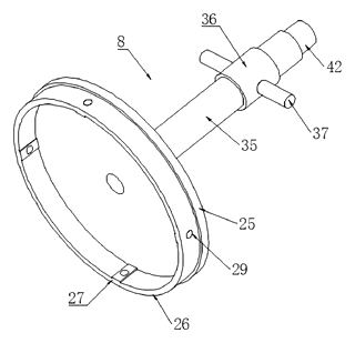
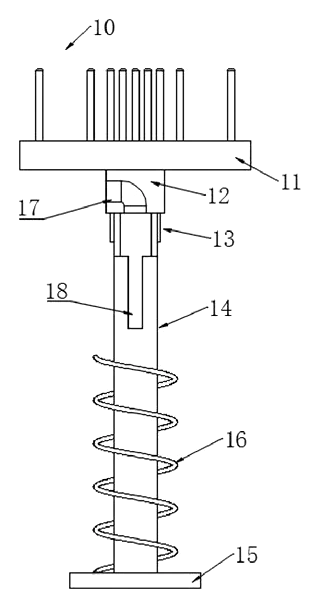
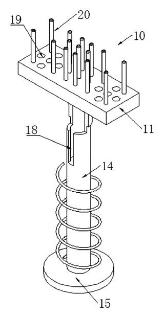
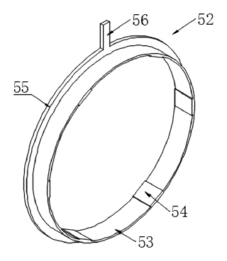
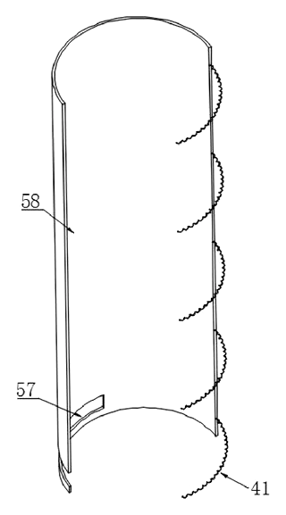
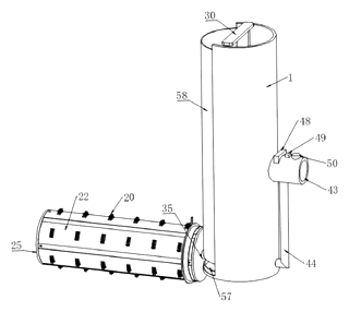
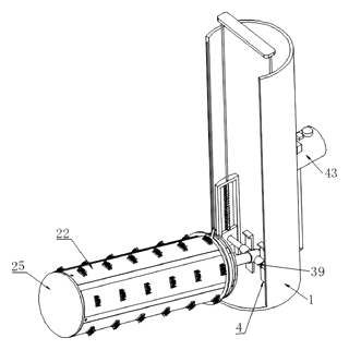
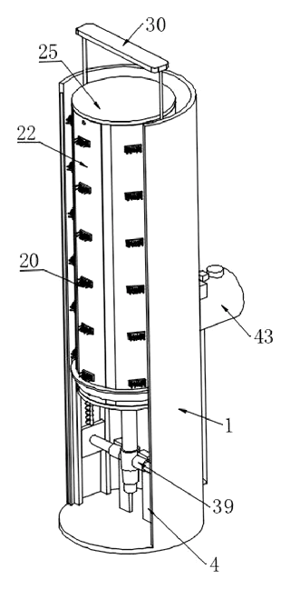
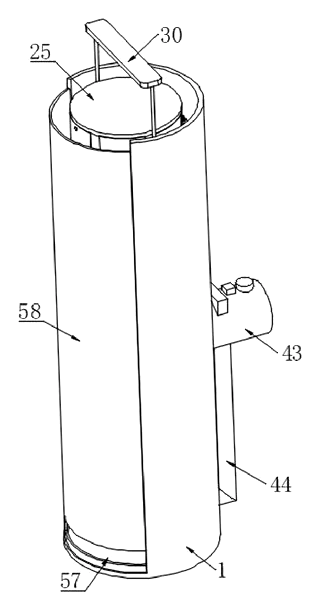
Drawings reproduced from the public patent document for reference.