
Patent CN118121117B
Updated November 5, 2026Automatic Floor Scrubber with Sticky Pollutant Detection and Retractable Cleaning Mechanism
Standard floor scrubbers use rotating brushes that cannot remove adhered items like chewing gum or wet paper towels, forcing manual intervention. This design integrates a pollutant detection module that identifies sticky contaminants. When detected, the control system activates a cleaning mechanism mounted on the brush plate. The mechanism uses two nested telescopic sleeves and a reciprocating rotating rod driven by the brush plate's motion. As the rod rotates, it moves through spiral and straight grooves in the sleeves, extending the scrapers to contact the ground and retracting them when clean, automating the removal of stubborn residues without stopping the machine.
- China invention patent - in force
- No filings outside China
- Commercial cleaning equipment
- Telescopic scraper mechanism, sensor-controlled engagement
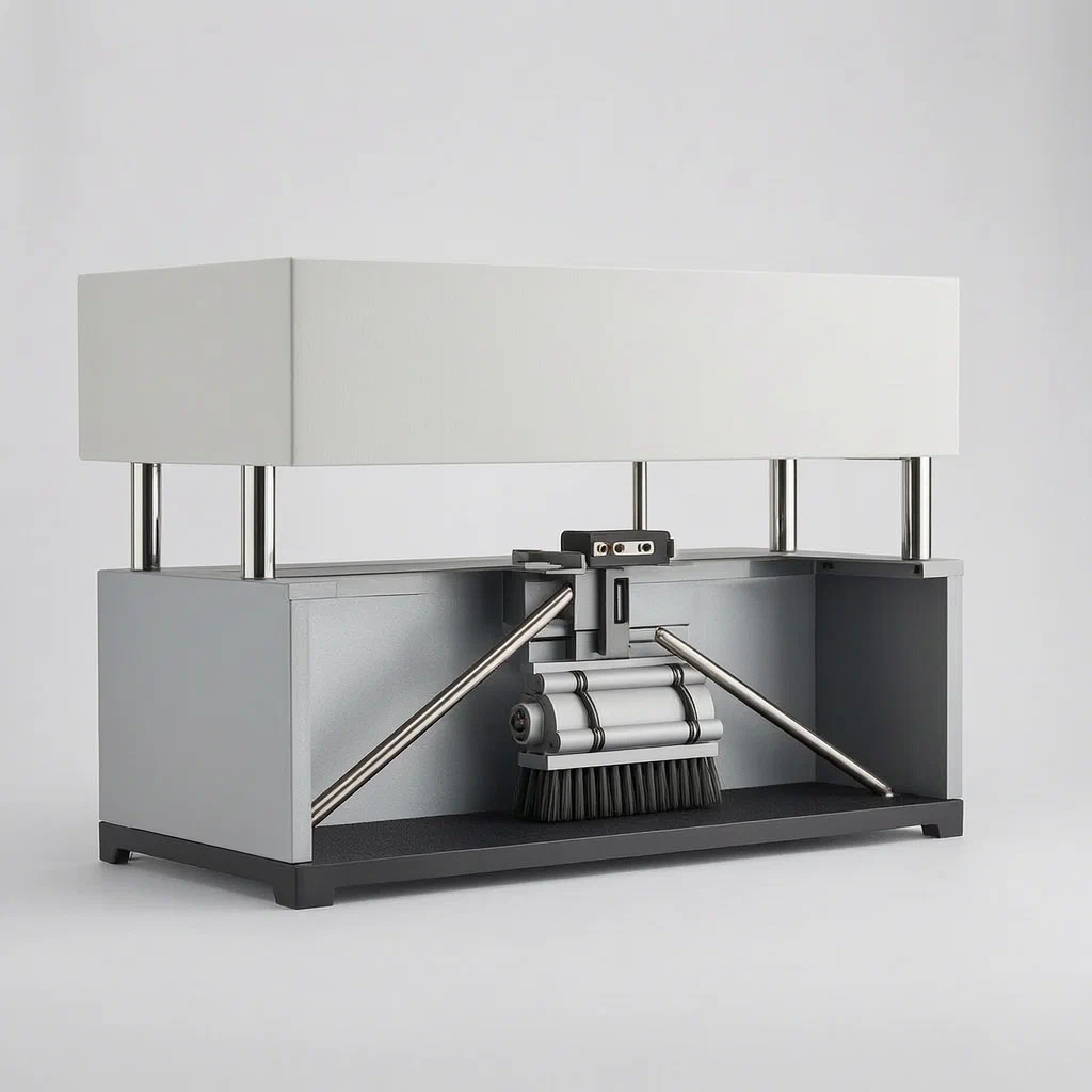
Splat! What let you down?
👁️
Sticky pollutant detection
A dedicated module identifies gum or paper stuck to floors and signals the controller.
⬇️
Auto-engaging scrapers
Telescopic sleeves extend scrapers to the ground only when sticky residue is detected.
🔄
Brush-driven cam action
The existing brush plate rotation drives the reciprocating rods that extend the mechanism.
🧹
Spiral groove guidance
Nested sleeves use spiral and straight grooves to convert rotation into precise vertical movement.
Bring this product to market
- ✓ Patent review Patent family and legal status reviewed in the relevant jurisdictions.
- 2 Product brief · now How it works, uses and options written up
- 3 Prototype First samples for buyers to review
- 4 Pilot run Small first batch for launch customers
- 5 Volume production Repeat orders at scale
Buyer interest
– of 100 buyers needed to start prototyping
One click, no sign-up. Each vote is one real visitor, and products with the most interest go to prototyping first.
Build team: no members yet. Need a partner, co-funding or skills to build this? Join and we introduce the team once it forms.
Patent Rights & Team Participation
Before joining a development team, participants should ensure they have the necessary rights or authorization to participate in the project.
Participation is generally appropriate where:
- You own the relevant patent rights or have obtained permission or a license from the rights holder.
- The relevant patent rights have expired or have been legally invalidated in the jurisdictions where the planned activities will take place.
- The planned development, manufacturing, and commercialization activities have been independently assessed and do not infringe applicable patent rights in the relevant jurisdictions.
Important: Being located outside a country where a patent is protected does not automatically exempt you from patent infringement risks. Patent rights may apply based on where development, manufacturing, use, sale, or import activities take place.
IP2M does not grant any patent license or authorization through team participation. Joining a project does not provide permission to use, manufacture, or commercialize patented technology.
The problem
Automatic floor scrubbers are efficient for general dust and liquid spills, but they struggle with adhered contaminants. Items like chewing gum, dried mud clumps, or wet paper towels stick firmly to hard floors. The standard rotating brush heads used in these machines cannot scrape off these sticky pollutants effectively. Consequently, operators must stop the machine and manually remove the debris, which reduces productivity in large public spaces such as airports, shopping malls, and railway stations where such litter is common.
The solution
This patent describes an automatic floor scrubber and dryer that adds a specific cleaning module to handle sticky pollutants. The system comprises a control terminal, the main scrubber body, a pollutant detection module, and a cleaning mechanism attached to the brush plate.
- The pollutant detection module scans the ground ahead of the machine. It identifies whether sticky pollutants are present.
- If a pollutant is detected, the control terminal sends a command to the cleaning module.
- The cleaning mechanism consists of two telescopic parts (sleeves) and a reciprocating rotating part. One sleeve slides inside the other.
- Each sleeve has a slide groove containing both a spiral section and a straight section. These sections are not connected within the same sleeve.
- A reciprocating rotating rod is inserted into these grooves. The other end of the rod connects to the brush plate.
- As the brush plate rotates, it drives the reciprocating part. The movement of the rod within the spiral groove causes the telescopic sleeves to extend downward, pressing a scraper against the ground.
- Once the sticky pollutant is scraped off, the detection module confirms the area is clear. The control terminal then reverses the action, or the geometry of the straight groove allows the sleeves to retract, lifting the scraper away from the floor.
Who it is for
- Facility management companies operating in high-traffic public venues like airports, train stations, and shopping centers where litter is frequent.
- Commercial cleaning equipment distributors looking for differentiated products that solve the specific pain point of manual gum removal.
- Municipal service providers responsible for maintaining public squares and pedestrian zones who need automated solutions for mixed debris.
- Industrial plant managers in areas where packaging materials or adhesives might drop onto concrete floors, requiring robust cleaning beyond standard mopping.
How it works
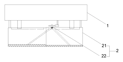
The main parts
The core innovation lies in the mechanical linkage between the existing brush drive and the new scraping function.
| No. | Part | What it does |
|---|---|---|
| 1 | Brush Plate | Rotates normally to scrub floors; also drives the cleaning mechanism. |
| 2 | Cleaning Mechanism | Assembly that extends and retracts to scrape sticky items. |
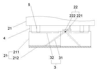
| - | Telescopic Sleeves | Two nested tubes; one slides inside the other. |
| - | Slide Grooves | Paths inside the sleeves (spiral + straight) guiding the rod. |
| - | Reciprocating Rod | Connects the brush plate to the sleeves; moves up/down as it rotates in the groove. |
| - | Scraper | Triangular blade at the bottom of the outer sleeve; contacts the floor. |
| - | Limit Block | Fixed on the brush plate; interacts with the straight groove to lock position. |
Operating steps
- Detection: The machine moves forward. The sensor checks the floor. If normal dirt is seen, it continues standard scrubbing.
- Trigger: If sticky pollutant data is uploaded to the control terminal, it issues a command.
- Extension: The motor driving the brush plate continues to rotate. Through the connection block, this rotation drives the reciprocating rod.
- Cam Action: The rod moves along the spiral groove of the inner sleeve. This converts rotational motion into linear extension of the telescopic sleeves.
- Scraping: The triangular scraper presses against the ground, removing the gum or paper.
- Retraction: When the sensor indicates the pollutant is gone, or after a set cycle, the mechanism retracts. The rod moves into the straight groove, locking the sleeves in the raised position so they do not drag on clean floors.
Applications
Airports and Transit Hubs
High foot traffic leads to dropped gum and fast-food wrappers. The detector triggers the scraper automatically, reducing the need for staff to bend down and pick up debris while the machine is running.
Shopping Malls and Retail Floors
Polished stone or tile floors often accumulate sticky residues from spilled drinks or candy. This system maintains the shine by removing adhered particles that brushes alone leave behind.
Food Courts and Dining Areas
Wet napkins and food scraps can stick to flooring. The automated engagement ensures these specific types of waste are cleared efficiently during routine cleaning cycles.
Industrial Warehouses
Packaging tape remnants or adhesive labels can adhere to concrete floors. The robust scraper mechanism handles these tough residues without interrupting the workflow of the cleaning crew.
Where it is less suitable
- Carpeted Areas: The scraper mechanism is designed for hard floors; it would damage carpet fibers and is ineffective on soft surfaces.
- Very Low Traffic Zones: For areas rarely visited, the cost and complexity of the detection and mechanical system may not justify the benefit over simple manual spot cleaning.
- Uneven or Textured Floors: The fixed-length travel of the scraper assumes a relatively flat surface; highly irregular terrain might prevent consistent contact or cause jamming.
Patent & Production
At a glance
| Patent number | CN118121117B (application CN202410440428) |
| Type | China invention patent (发明专利) - protects product structure and method |
| Original title | Automatic floor scrubber and dryer (一种自动洗地吸干机) |
| Patent owner | Guangdong Haoyu Cleaning Environmental Protection Equipment Co ltd |
| Inventors | Huang Yanhong, Huang Haozhao |
| Filing date | 2024-04-12 |
| Grant date | 2024-11-19 |
| Status (China) | In force - valid until at most 2044-04-12, subject to payment of annual fees |
| Patent family | Public record shows Chinese filings only - no US, European, Japanese, PCT or other filings listed |
| Cited by | 0 later documents |
| Source | Google Patents (search for CN118121117B) |
What the claims cover, in plain language
Claim 1 defines an automatic floor scrubber and dryer comprising a control terminal, a body module, and a cleaning module on the brush plate. Key elements include a pollutant detection module that identifies sticky pollutants and uploads data to the control terminal. The terminal commands the cleaning module to move a cleaning mechanism toward or away from the ground. The mechanism includes two telescopic parts (one sliding inside the other) and a reciprocating rotating part. Both telescopic parts have slide grooves (spiral and straight sections). The rotating part connects to the brush plate and moves within the grooves to extend/contract the sleeves. The brush plate drives the sleeves synchronously. Specific structural details include a triangular scraper, a limit block on the brush plate engaging the straight groove, and the sleeve length being smaller than the brush disc width.
Claims 2-8 add further specifications: pressure detection parameters in the control terminal; the triangular shape of the scraper; dimensional constraints of the sleeve; the composition of the reciprocating part (slide rod and connecting block); the driving mechanism for the connecting block; diameter matching of the rod and groove; and the rotation angle limit (≤180°).
This is a simplified reading for orientation only. The legal scope is defined by the exact claim wording in the official Chinese document.
What this means for US production
This patent was filed in China and is currently in force. The public record shows no US or other foreign counterpart.
Two points to settle early:
- Other patents may exist. Commercial floor scrubbers are a competitive field with numerous active patents regarding sensor integration and mechanical linkages. While no direct citations are listed here, a freedom-to-operate (FTO) review is recommended to ensure the specific combination of detection-triggered telescopic scraping does not infringe on existing US utility patents held by major equipment manufacturers.
- Sensor Standardization. The patent mentions a “pollutant detection module” but does not specify the sensor technology (e.g., optical, capacitive). The choice of sensor affects the FTO landscape significantly, as different sensing methods may be covered by separate patents.
Customization and manufacturing
What can be customized
| Area | Options |
|---|---|
| Detection Module | Type of sensor (optical camera, IR, or capacitive) based on target pollutant types |
| Scraper Material | Stainless steel, hardened polymer, or rubber-edged blades depending on floor type |
| Control Logic | Sensitivity thresholds for “sticky” detection and response time delays |
| Mechanism Geometry | Sleeve length, groove pitch, and stroke depth to match specific brush plate sizes |
| Integration | Mounting brackets for existing scrubber models vs. new chassis designs |
Things to plan for (US market)
- OSHA / NIOSH Guidelines: Ensure the moving parts (telescopic sleeves) are guarded to prevent pinch hazards during operation.
- Electrical Safety: UL certification for battery-powered or mains-connected units, particularly if the control terminal interfaces with external power sources.
- Battery Transport: UN 38.3 testing required for shipping lithium-ion batteries if the unit is cordless.
- EMC: FCC Part 15 compliance for the wireless communication between the detection module and control terminal if applicable.
How a project runs
- Inquiry - Define the base scrubber model, desired detection accuracy, and quantity.
- Design - Adapt the telescopic mechanism dimensions to fit the specific brush plate diameter and housing constraints. Select appropriate sensors.
- Prototype - Build functional samples to test the cam-action reliability and sensor trigger logic.
- Pilot Run - Validate durability of the scraper and sleeve interface under repeated extension/retraction cycles.
- Production - Manufacture sleeves, rods, and housings; assemble with electronics and brush motors.
Quantities & timeline
Tooling for the plastic/metal sleeves and the reciprocating rods requires precision molds or machining fixtures. The complexity lies in aligning the spiral grooves with the rotating drive. Development time focuses on tuning the sensor algorithm and mechanical tolerances. Send us your base model specs, sensor preferences, quantity and target price and we will reply with options.
Production notes
Tooling and process
Injection molding is likely used for the sleeve bodies and connecting blocks to achieve complex internal groove geometries. Metal stamping or extrusion may form the scraper blades and structural supports. Motor assembly involves integrating the drive units with the control terminals.
Cost drivers
Part count increases due to the nested sleeves and guide rods. Number of molds depends on whether multiple scrubber sizes share components. Material grade selection (e.g., wear-resistant polymers vs. standard ABS) impacts tool life and part durability. Surface finish requirements for metal parts affect corrosion resistance.
Prototyping path
Start with a 3D model to check interference between the spiral grooves and the reciprocating rod. Use 3D-printed bodies for initial fit and handling tests. CNC-machined parts may be needed for the stressed sleeve sections before committing to injection molds. Functional sample testing validates the sensor-to-mechanism latency.
What we would change before tooling
We would likely verify the alignment tolerance of the slide rod within the spiral groove to prevent binding. Adjust the limit block interaction to ensure smooth transition between spiral and straight groove phases. Confirm the scraper angle optimizes contact pressure without damaging sensitive floor finishes.
Common failure points
Thin walls in the sleeves could warp or sink, altering the groove path. Shaft and bearing alignment issues may cause the reciprocating motion to jam. Coating wear at contact points between the rod and groove reduces efficiency over time. Trapped water or residue in the crevices of the telescopic joints could hinder retraction.
Patent drawings
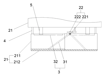
Drawings reproduced from the public patent document for reference.
Frequently asked questions
How does the machine know when to deploy the scraper?
A dedicated pollutant detection module scans the floor ahead of the cleaning path. When it identifies characteristics of sticky pollutants (such as chewing gum or wet paper), it sends data to the control terminal. The terminal then issues a command to activate the cleaning mechanism.
Does the scraper stay down all the time?
No. The mechanism is designed to retract when no sticky pollutants are detected. It uses a telescopic sleeve system driven by the rotation of the brush plate. When retracted, the scraper lifts off the ground to avoid unnecessary wear or damage to clean floors.
Can it work with any floor type?
It is primarily designed for hard floors like concrete, tile, stone, and vinyl. The triangular scraper needs a flat surface to maintain proper contact. It is not suitable for carpets or heavily textured surfaces where the mechanism might jam or fail to seal against the ground.
What happens if the sensor makes a mistake?
If the sensor falsely detects a pollutant, the scraper will extend unnecessarily. This may increase wear on the scraper tip but typically does not damage the floor. If it misses a pollutant, the item remains on the floor until the next pass or manual intervention. Calibration of the detection sensitivity is part of the setup.
Is the maintenance difficult?
The telescopic sleeves and guide rods contain moving parts that require periodic inspection. Debris accumulation in the grooves could hinder movement. Regular cleaning of the sensor lens and checking the scraper blade condition are recommended. The design avoids complex hydraulic systems, relying on mechanical cams driven by the existing motor.
Can this design be made and sold in the US?
The patent is in force in China. The public record shows no US counterpart, so it does not restrict the design in the US. However, commercial floor cleaning equipment is a crowded patent field. We recommend a freedom-to-operate (FTO) review to ensure no other US patents cover similar sensor-integrated mechanisms before volume production.
Are you affiliated with the patent owner?
No. IP2M is an independent design and manufacturing service working from the public patent document.
Request a quote
Click Request a Quote below to see our email address - copy it, or open your email app with a ready-made message. Please mention patent CN118121117B in the subject.
Helpful details to include:
- Your company and channel (facility services, equipment distributor, industrial user)
- Base scrubber model you want to retrofit or integrate with
- Target pollutants (gum, tape, paper) to help select sensor type
- Estimated quantity and target price
- Timeline - when you would like prototypes and first shipment
You can also reach us at (332) 203-9997.
Page editor: Daniel Chen, Product Research Editor · IP2M
Last updated November 5, 2026. If something on this page looks wrong, email [email protected] and we will check it against the patent.
Interested in building this?
Tell us your target market, quantity and timeline. We reply with options for prototyping, small-batch runs or volume production.
Send your inquiry to
Please put CN118121117B in the subject line and tell us your company, country, estimated quantity and timeline.
Prefer to talk? Call (332) 203-9997.
More product-ready patents
All Home, Kitchen & Cleaning patents →
Home, Kitchen & Cleaning
Self-Wringing Flat Mop with Fold-Away Wringer
Flat mop with a built-in wringer that opens only when you wring and folds flat against the pole when you mop.
Patent CN207734114U
Home, Kitchen & Cleaning
Magnetic Double-Sided Window Cleaner with Dial-Set Magnet Strength
Magnetic window cleaner with a sealed, sliding magnet, dial-set strength for different glass thicknesses and a spring-held idle position.
Patent CN209360543U
Home, Kitchen & Cleaning
Metal Kettle with Magnetic Lid That Stays On When Pouring
Metal teapot/kettle with a magnet-held lid that does not fall off when pouring, and an insulated, vented lid knob.
Patent CN210540477U
Home, Kitchen & Cleaning
Reinforced Disposable Soup Spoon
Disposable soup spoon with a handle-to-bowl rib, stiffened edges and a ring foot to resist breaking.
Patent CN206964482U
Home, Kitchen & Cleaning
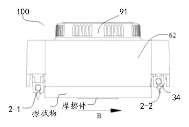
Self-Switching Double-Squeegee Window Cleaner
Cleaning head with two squeegee blades that switch automatically with the direction of movement.
Patent CN212630655U
Home, Kitchen & Cleaning
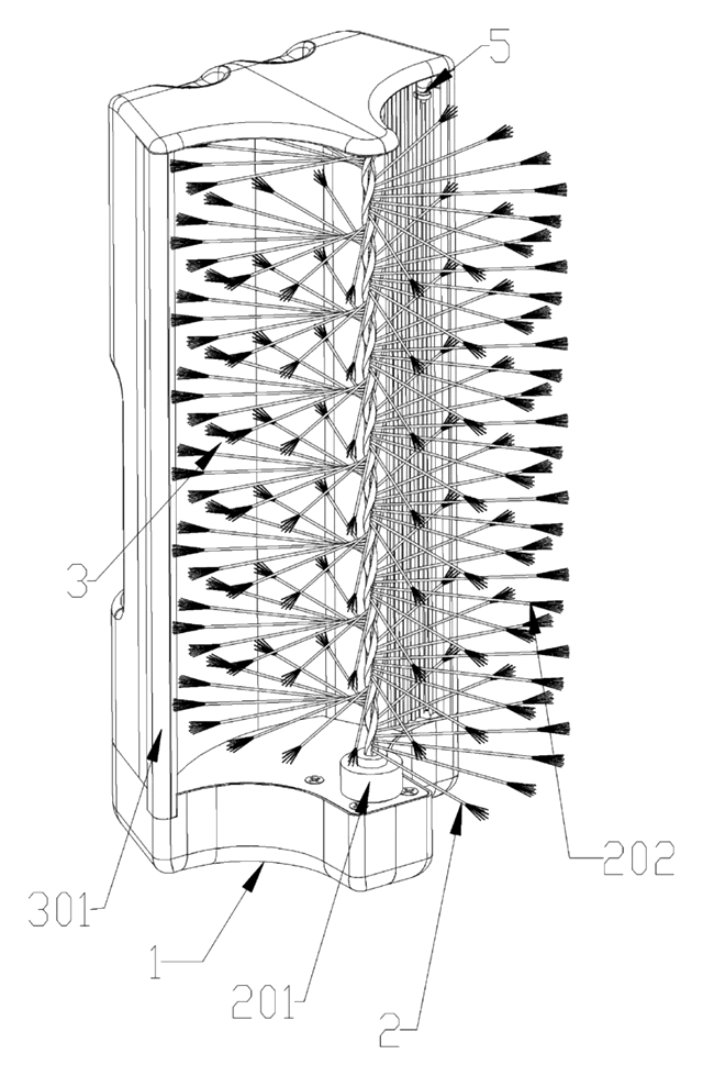
Self-Rinsing Roller Scrub Brush with Dirty-Water Tank
Powered roller brush that rinses and spins its bristles clean inside the body and stores the dirty water.
Patent CN210076909U
Browse by category
- Apparel & Accessories (41)
- Baby & Kids (26)
- Bags & Luggage (15)
- Bath & Personal Care (27)
- Car Accessories (22)
- Furniture, Bedding & Storage (21)
- Garden & Outdoor (29)
- Health & Wellness (12)
- Home, Kitchen & Cleaning (44)
- Lighting (21)
- Packaging & Containers (11)
- Pet Products (10)
- Phone & Camera Accessories (8)
- Retail Display (22)
- School, Office & Art (31)
- Sports & Recreation (40)
- Tools & Workshop (49)
- Toys & Games (20)
This page is based on the public patent document CN118121117B, assigned to Guangdong Haoyu Cleaning Environmental Protection Equipment Co ltd. IP2M is an independent manufacturing service and is not affiliated with, endorsed by or licensed by the patent owner. Images marked as concept renderings are illustrations, not photos of an existing product. Patent status information is provided for reference only and is not legal advice; confirm freedom to operate for your market before production. Full disclaimer.