
Patent CN118144688B
Updated October 31, 2026Automobile Luggage Rack with Spring-Brake Crossbars and Folding Rear Gate
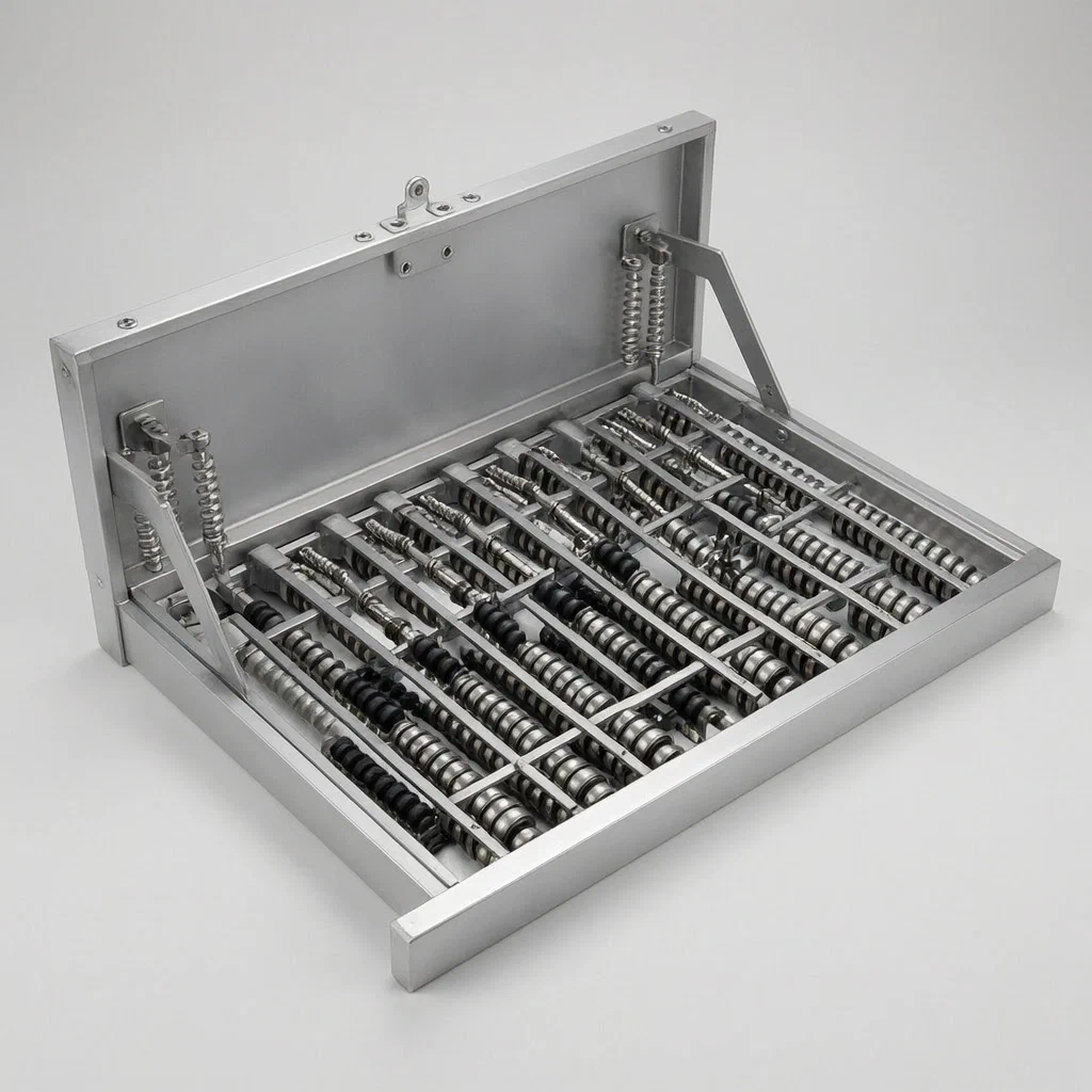
Standard roof racks often require straps or separate locking mechanisms to keep luggage from shifting or sliding off during braking. This design integrates the retention system directly into the frame structure. A U-shaped base holds the load, while a rear baffle acts as both a gate for easy access and a trigger for the internal locking mechanism. When the baffle is closed, a pull rope linked to its rotating shaft drives a main rod forward. This action compresses springs on multiple branch rods, pushing upward-protruding brake blocks into fixed gaps between rollers on the upper support bars. These blocks physically jam the rollers, preventing any longitudinal movement of the cargo. When the baffle is opened for unloading, the springs expand, retracting the brake blocks and freeing the rollers to rotate, letting bags slide out smoothly without manual effort.
- China invention patent - active
- No filings outside China
- Folding loading surface
- Mechanical spring brake system
Splat! What let you down?
🔒
Integrated Locking
Closing the rear gate automatically engages spring-loaded brakes on the crossbars.
📦
Easy Unloading
Opening the gate retracts the brakes, allowing luggage to slide out freely.
⚙️
Roller Mechanism
Upper support rods feature paired rollers that are jammed by brake blocks.
🛡️
Full Enclosure
The U-frame and baffle create a rectangular boundary to contain cargo.
Bring this product to market
- ✓ Patent vetted China-only family and legal status checked
- 2 Product brief · now How it works, uses and options written up
- 3 Prototype First samples for buyers to review
- 4 Pilot run Small first batch for launch customers
- 5 Volume production Repeat orders at scale
Buyer interest
– of 100 buyers needed to start prototyping
One click, no sign-up. Each vote is one real visitor, and products with the most interest go to prototyping first.
Build team: no members yet. Need a partner, co-funding or skills to build this? Join and we introduce the team once it forms.
The problem
Traditional car roof racks rely on external accessories like ratchet straps, nets, or separate clamps to secure luggage. These methods are time-consuming to install and remove, and they can fail if not tightened correctly. Cargo may shift during acceleration or braking, causing noise, damage, or safety hazards. Additionally, loading heavy suitcases onto a high roof rack is difficult because items cannot be slid easily once placed; users must lift them vertically over the edge. There is a need for a rack structure that simplifies loading and unloading while providing an automatic, integrated method to prevent cargo movement without extra tools.
The solution
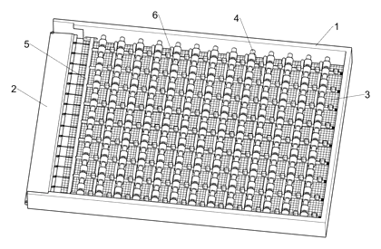
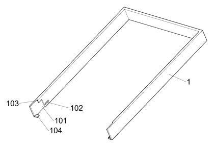
- A U-shaped frame (1) is mounted on the vehicle roof, forming a semi-enclosed tray.
- A rear baffle plate (2) hinges on the open side of the frame, completing a rectangular enclosure when standing upright.
- Inside the frame, upper support rods (6) run transversely, each fitted with pairs of rollers (601).
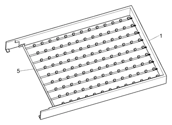
- Below these rods, a set of branch pull rods (501) carries upward-protruding brake blocks (502).
- These rods are connected to a main pull rod (5) which slides longitudinally within mounting grooves (102).
- Springs (503) connect the branch rods to the frame walls, biasing them toward a retracted position.
- A pull rope (204) links the rotating shaft (201) of the baffle to the main pull rod.
- When the baffle closes, it rotates the shaft, pulling the main rod forward against the spring tension, driving the brake blocks up into the gaps between the rollers to lock them.
Who it is for
- Automotive accessory brands looking for differentiated roof rack systems that offer ease-of-use features beyond standard rails.
- Outdoor gear manufacturers whose customers frequently load bulky camping equipment or sports gear and value quick setup.
- Vehicle customization shops installing premium storage solutions for SUVs and trucks where aesthetic integration and functional security are key.
- E-commerce sellers targeting consumers frustrated with loose straps and complex tie-down procedures for rooftop cargo boxes or soft bags.
How it works
The main parts
| No. | Part | What it does |
|---|---|---|
| 1 | U-shaped Frame | Main structural body mounted to the roof; contains mounting grooves. |
| 2 | Rear Baffle | Hinged gate that encloses the cargo area; triggers the locking mechanism. |
| 5 | Main Pull Rod | Slides longitudinally; transmits motion from the baffle to the branch rods. |
| 501 | Branch Pull Rods | Move laterally/vertically; carry the brake blocks. |
| 502 | Brake Blocks | Protrude upwards to jam between rollers when activated. |
| 503 | Springs | Retract the branch rods when the baffle opens. |
| 6 | Upper Support Rods | Hold the rollers; provide the surface for cargo to rest on. |
| 601 | Rollers | Allow cargo to slide; locked by interference with brake blocks. |
| 201 | Rotating Shaft | Pivot point for the baffle; winds/unwinds the pull rope. |
| 204 | Pull Rope | Connects the shaft rotation to the linear movement of the main rod. |
Operating Steps
- Loading: Place luggage on the upper support rods. The rollers are free to rotate because the baffle is open (springs extended, brakes retracted). Slide the bag to the desired position.
- Securing: Lift the rear baffle (2) to a vertical position. As it rotates around the shaft (201), the pull rope (204) pulls the main rod (5) forward.
- Locking Action: The movement of the main rod pushes the branch rods (501) inward/upward against the spring force (503). The brake blocks (502) rise and fit tightly into the fixed intervals between the pairs of rollers (601).
- Transport: With the rollers jammed, the upper support rods cannot rotate relative to the frame, effectively locking the cargo in place and preventing forward or backward sliding.
- Unloading: Release the locking mechanism (if electronic) or simply lower the baffle. The springs (503) expand, pulling the branch rods back and retracting the brake blocks from the roller gaps. The rollers become free again, allowing luggage to be slid off easily.
Applications
Family Road Trips
Families loading strollers, suitcases, and coolers benefit from the sliding capability. Once loaded, closing the gate secures everything instantly, eliminating the need for multiple strap adjustments before departure.
Camping and Overlanding
Campers carrying heavy canvas tents or wooden crates appreciate the rigid enclosure. The full surround prevents items from bouncing out on rough terrain, while the easy-release mechanism speeds up camp setup.
Sports Equipment Transport
Skiers or surfers using roof-mounted bags find this useful. The brake system keeps long items aligned and stationary, reducing wind noise and drag compared to loosely strapped gear.
Urban Commuter Storage
Commuters using rooftop boxes for work gear or shopping bags gain convenience. The mechanism allows one-handed operation (opening/closing the gate) to secure contents quickly between stops.
Where it is less suitable
- Flat-panel only racks: This design requires depth for the U-frame and internal mechanics; it is not suitable for slim, flat crossbar-only setups.
- Extreme off-road jumps: While it locks against sliding, it does not replace primary tie-downs for objects subject to high-G impact forces where lifting might occur.
- Very wide loads: The mechanism relies on lateral engagement across specific widths; oversized loads extending beyond the frame may not be secured by the central brake array.
Frequently asked questions
How does the locking mechanism actually work?
It is purely mechanical. When you close the rear gate (baffle), it turns a shaft. This shaft pulls a rope connected to a main rod inside the frame. The main rod pushes smaller branch rods up against spring pressure. These branch rods have blocks that pop up between rollers on the top bars, jamming them so your cargo cannot slide forward or backward. Opening the gate releases the tension, and the springs push the blocks down, freeing the rollers.
Do I need to use straps with this rack?
For normal driving conditions, the integrated brake system is designed to hold cargo in place, potentially reducing the need for frequent strap tightening. However, for extremely heavy items or off-road driving with significant vertical impacts, additional tie-downs are always recommended for maximum safety. The patent describes the stability benefits but does not explicitly exclude all external restraints.
Can it handle heavy suitcases?
The load capacity depends on the aluminum thickness and roller strength chosen during manufacturing. The patent does not specify a numerical weight limit. For US production, we would engineer the frame and rollers to meet typical consumer expectations, such as supporting 50-100 lbs per crossbar section, confirmed by prototype testing.
Is the mechanism durable?
The moving parts include springs, ropes, and sliding rods. We recommend using stainless steel cables instead of fabric ropes for longevity and nylon-lined bushings for the sliders. Regular cleaning of the mounting grooves to prevent dirt buildup ensures the mechanism continues to operate smoothly over years of use.
How hard is it to install on my car?
Installation involves mounting the U-shaped frame to your existing roof rails or tracks. The internal mechanism is pre-assembled at the factory. Users do not need to adjust the internal springs or rods; they simply attach the frame to the vehicle. Specific mounting brackets can be customized for different car models.
Can this design be made and sold in the US?
The patent is currently in force in China only. Since there are no corresponding US patents, the specific technical solution described here is not protected by patent law in the United States. However, you should still conduct a freedom-to-operate search to ensure no other existing US patents cover similar roof rack locking mechanisms.
Are you affiliated with the patent owner?
No. IP2M is an independent design and manufacturing service working from the public patent document.
Request a quote
Click Request a Quote below to see our email address - copy it, or open your email app with a ready-made message. Please mention patent CN118144688B in the subject.
Helpful details to include:
- Your company and channel (auto accessory brand, outdoor retailer, e-commerce seller)
- Target vehicles (specific models or universal fitment)
- Load capacity requirements (lbs/kg)
- Material preferences (aluminum grade, finish color)
- Estimated quantity and target price
- Timeline - when you would like samples and the first shipment
You can also reach us at (332) 203-9997.
Explore this product
Interested in building this?
Tell us your target market, quantity and timeline. We reply with options for prototyping, small-batch runs or volume production.
Send your inquiry to
Please put CN118144688B in the subject line and tell us your company, country, estimated quantity and timeline.
Prefer to talk? Call (332) 203-9997.
More product-ready patents
All Car Accessories patents →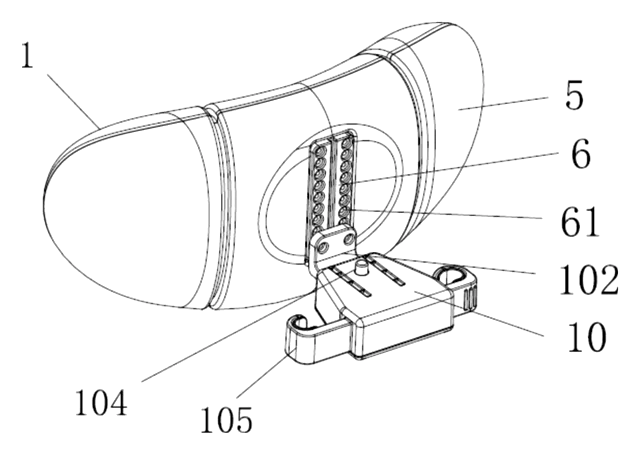
Car Accessories
Car Headrest Pillow with Ratchet Side Wings and Push-Button Reach
Post-mounted car headrest pillow with ratchet side wings and a push-button forward adjustment.
Patent CN212195197U
Car Accessories
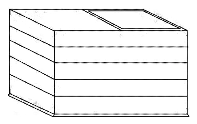
Hard-Shell Rooftop Tent That Doubles as a Cargo Box
Roof box whose hard frames lift on gas struts into a tent with door and skylight, and fold back for luggage.
Patent CN206327275U
Car Accessories
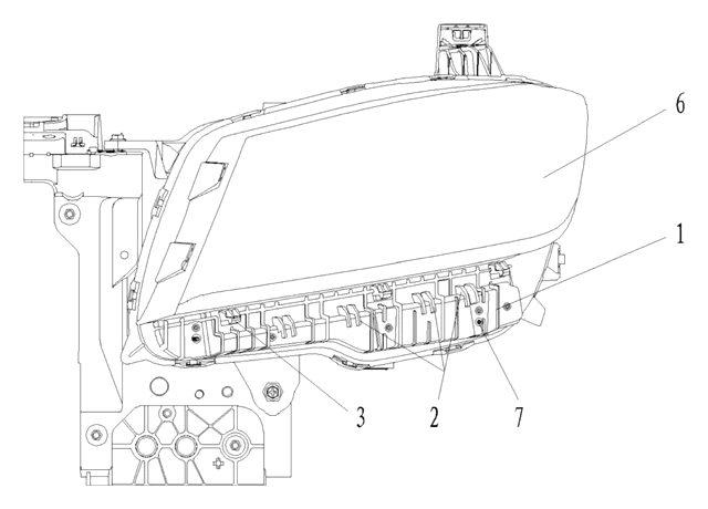
Headlamp-to-Bumper Adapter Bracket That Sets Gap and Flush in Three Directions
Molded bracket under the headlamp: support blocks and snap teeth locate the bumper flange for an even gap.
Patent CN216580316U
Car Accessories
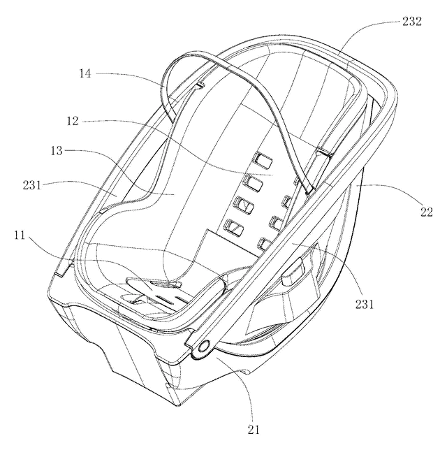
Infant Car Seat with a Load-Bearing Base That Wraps the Carrier
Infant car seat whose base has a backrest and swing-up side rails, so the carrier can be lighter.
Patent CN206383856U
Car Accessories
Retractable Side Impact Protection Block for Child Car Seats
Retractable side-impact block for child seats: springs out to provide side-impact buffering, folds flat.
Patent CN207028930U
Car Accessories
Rain-Deflecting Side Mirror with a Pivoting Air-Guide Plate
Side mirror with a top air duct and folding guide plate that directs airflow across the glass.
Patent CN207345672U
Browse by category
- Apparel & Accessories (23)
- Baby & Kids (18)
- Bags & Luggage (12)
- Bath & Personal Care (18)
- Car Accessories (14)
- Furniture, Bedding & Storage (13)
- Garden & Outdoor (19)
- Health & Wellness (9)
- Home, Kitchen & Cleaning (27)
- Lighting (13)
- Packaging & Containers (7)
- Pet Products (6)
- Phone & Camera Accessories (4)
- Retail Display (15)
- School, Office & Art (20)
- Sports & Recreation (26)
- Tools & Workshop (32)
- Toys & Games (13)
This page is based on the public patent document CN118144688B, assigned to Jiangxi Huasheng Aluminum Co ltd. IP2M is an independent manufacturing service and is not affiliated with, endorsed by or licensed by the patent owner. Images marked as concept renderings are illustrations, not photos of an existing product. Patent status information is provided for reference only and is not legal advice; confirm freedom to operate for your market before production. Full disclaimer.