At a glance
| Patent number | CN118144688B (application CN202410571443) |
| Type | China invention patent (发明专利) - protects product shape, structure, and process |
| Original title | Automobile luggage rack (一种汽车行李架) |
| Patent owner | Jiangxi Huasheng Aluminum Co ltd |
| Inventors | Wang Gang, Qing Lingbin |
| Filing date | 2024-05-10 |
| Grant date | 2024-07-19 |
| Status (China) | In force - valid until at most 2044-05-10, provided annual fees are paid |
| Patent family | Chinese filings only - no US, European, Japanese, PCT or other filings listed |
| Cited by | 0 later documents |
| Source | Google Patents (search for CN118144688B) |
What the claims cover, in plain language
Claim 1 defines a car luggage rack comprising a U-shaped frame (1) and a baffle (2) rotatably mounted on the opening side. Together they form a rectangular enclosure. A locking mechanism connects them. Key internal components include mounting grooves (102) in the frame walls housing a main pull rod (5) that reciprocates. Attached to the main rod are branch pull rods (501) equipped with upward brake blocks (502) and biased by springs (503). Above these are upper support rods (6) with pairs of rollers (601). A pull rope (204) links the baffle’s rotating shaft (201) to the main rod. Rotating the baffle moves the main rod, causing the brake blocks to engage or disengage the rollers to lock or release cargo.
Claim 2 specifies end grooves (101) in the frame walls where the ends of the rotating shaft sit. Claim 3 details the locking mechanism as a locking groove (103) in the frame and a lock head (202) on the baffle. Claim 4 adds bearing plates (104) at the frame ends to support/buffer the falling baffle. Claim 5 onward describe further structural refinements of the shaft and linkage components.
This is a simplified reading for orientation only. The legal scope is defined by the exact claim wording in the official Chinese document.
What this means for US production
This patent was filed only in China and is currently in force. Making, selling, or importing this specific design in China requires permission from the patent owner. It has no US or other foreign counterpart.
Two points to settle early:
- Other patents may exist. Automotive roof racks are a crowded field with numerous global patents covering crossbar designs, locking mechanisms, and aerodynamic profiles. A freedom-to-operate (FTO) review is essential to ensure your version does not infringe on existing US or international IP, particularly regarding the mechanical linkage and roller-brake interaction.
- Material and Process. The patent focuses on the linkage and does not specify material grades. Manufacturing process (extrusion vs. casting) and alloy choice are open and affect cost and strength.
Customization and manufacturing
What can be customized
| Area | Options |
|---|---|
| Frame Material | 6061-T6 Aluminum extrusion, steel tube, or composite polymer |
| Dimensions | Length and width adjusted to fit specific vehicle roof rails or track systems |
| Finish | Anodized black/silver, powder-coated, or painted |
| Locking Control | Manual latch, keyed cylinder, or electronic remote control (as hinted in description) |
| Roller Type | Nylon, Teflon, or metal bearings for different weight capacities |
| Spring Rate | Adjusted for ease of operation vs. holding force |
Things to plan for (US market)
- FMVSS 209 / SAE J321: While primarily for seatbelts, similar dynamic testing principles apply to cargo retention systems to prove they hold under deceleration forces.
- DOT Compliance: Ensure the rack does not obscure license plates or exceed height limits specified by state laws.
- Corrosion Resistance: ASTM B117 salt spray testing is standard for automotive exterior components exposed to road salts and weather.
- UV Stability: Plastic components (rollers, ropes) must withstand prolonged sun exposure without degrading.
How a project runs
- Inquiry - Vehicle compatibility list, load capacity requirements, and quantity.
- Design - CAD modeling of the U-frame, linkage geometry, and roller spacing.
- Prototype - CNC machined samples to test the smoothness of the baffle-triggered locking action.
- Pilot Run - Durability testing (cycle life of springs/ropes) and vibration table tests.
- Production - Extrusion cutting, stamping, injection molding for plastic parts, assembly, and QC.
Quantities & timeline
Tooling costs depend heavily on whether the frame is custom-extruded or cut from standard stock. Injection molds for the brake blocks and rollers add upfront cost. Testing cycles for spring fatigue and corrosion resistance take several weeks. Send us your target vehicle models, load capacity, finish preference, estimated volume and we will reply with options.
Patent drawings
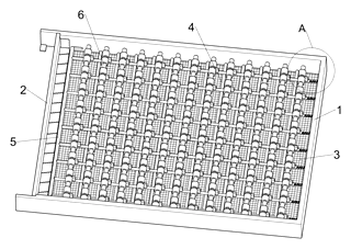
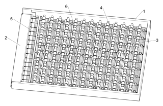
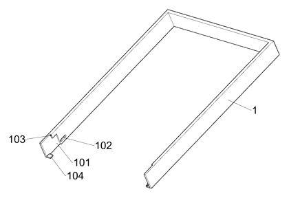
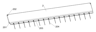
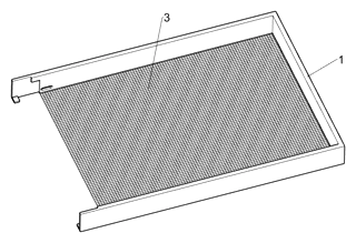
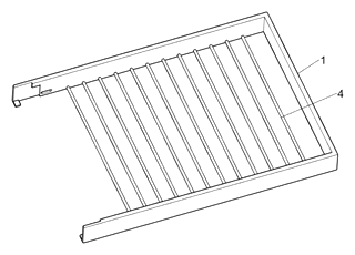
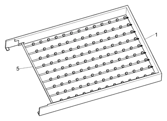
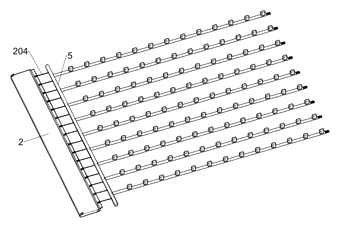
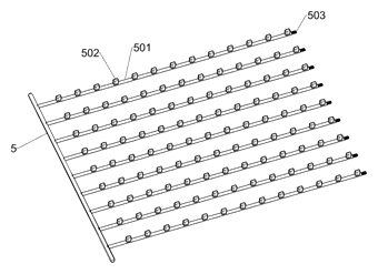
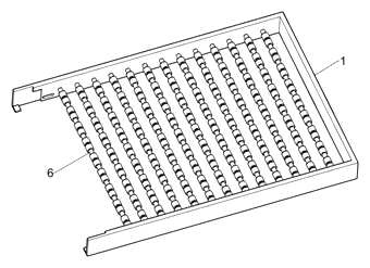
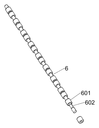
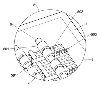
Drawings reproduced from the public patent document for reference.