
Patent CN118149126B
Updated November 8, 2026Automated Valve Seat Fastening Fixture for Ball Valves
Manual assembly of ball valves is slow and prone to misalignment errors, especially when fitting precision-machined seats into hemispherical sealing cavities. This automated fixture solves this by locking the valve body in place and using a coordinated system of gears, racks, and magnetic sliders to push and screw the valve seats into position simultaneously, ensuring consistent torque and alignment without manual intervention.
- China invention patent - active
- No filings outside China
- Valve manufacturing automation
- Motorized fixtures with magnetic sliders
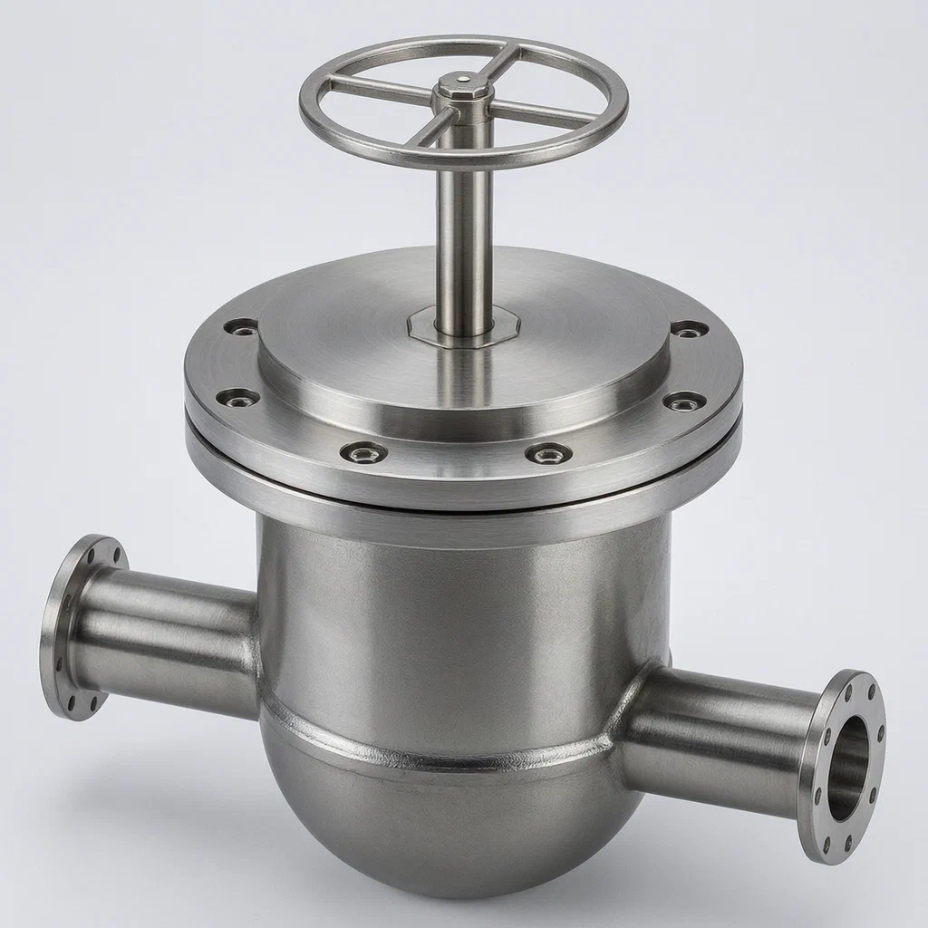
Splat! What let you down?
🔧
Dual-Seat Alignment
Simultaneously drives two opposing valve seats into the body using a central gear and dual racks.
🧲
Magnetic Retraction
Uses fixed and movable magnets to control the extension and retraction of limiting arc blocks.
⚙️
Intermittent Gear Drive
A half-gear mechanism controls vertical rod positioning before seat insertion begins.
🔄
Rotary Telescopic Rods
Second motors rotate telescopic rods to screw the seats fully home after initial pressing.
Bring this product to market
- ✓ Patent review Patent family and legal status reviewed in the relevant jurisdictions.
- 2 Product brief · now How it works, uses and options written up
- 3 Prototype First samples for buyers to review
- 4 Pilot run Small first batch for launch customers
- 5 Volume production Repeat orders at scale
Buyer interest
– of 100 buyers needed to start prototyping
One click, no sign-up. Each vote is one real visitor, and products with the most interest go to prototyping first.
Build team: no members yet. Need a partner, co-funding or skills to build this? Join and we introduce the team once it forms.
Patent Rights & Team Participation
Before joining a development team, participants should ensure they have the necessary rights or authorization to participate in the project.
Participation is generally appropriate where:
- You own the relevant patent rights or have obtained permission or a license from the rights holder.
- The relevant patent rights have expired or have been legally invalidated in the jurisdictions where the planned activities will take place.
- The planned development, manufacturing, and commercialization activities have been independently assessed and do not infringe applicable patent rights in the relevant jurisdictions.
Important: Being located outside a country where a patent is protected does not automatically exempt you from patent infringement risks. Patent rights may apply based on where development, manufacturing, use, sale, or import activities take place.
IP2M does not grant any patent license or authorization through team participation. Joining a project does not provide permission to use, manufacture, or commercialize patented technology.
The problem
In the manufacturing of ball valves, assembling the valve seats requires precise alignment and significant force. Traditional methods often rely on manual pressing or simple mechanical jigs that do not synchronize the movement of both sides. This can lead to uneven seating, where one side binds against the hemispherical sealing cavity while the other is loose. Furthermore, manually screwing the locking external threads into the internal channels is time-consuming and inconsistent, resulting in potential leaks or structural weakness in the final product.
The solution
The patented fixture addresses these issues through an integrated automated system:
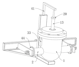
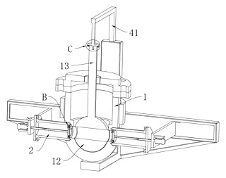
- A tool rack holds the valve body securely via an arc-shaped limiting block.
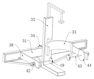
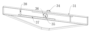
- Two valve seat limiting discs approach the body from opposite sides, driven by a first driving motor connected to a central driving gear and two driven racks.
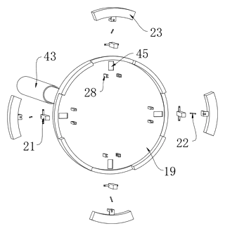
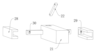
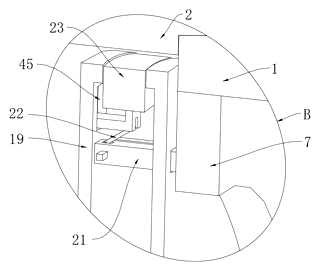
- Magnetic sliders (fixed and movable blocks) control the pushing long rods, which operate limiting arc blocks to guide the seats.
- Once pressed, a second driving motor rotates telescopic rods to screw the seats into the final locked position.
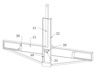
- A half-gear mechanism coordinates the vertical valve rod’s placement before the seats are inserted.
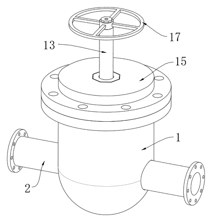
Who it is for
- Ball valve manufacturers seeking to reduce labor costs and increase assembly consistency in high-volume production lines.
- Industrial automation integrators looking for specialized end-of-arm tooling solutions for fluid control hardware.
- Quality assurance teams requiring precise, repeatable torque application during valve seat installation.
- OEM factories producing standardized valve sizes where rapid changeover between units is critical.
How it works
The main parts
| No. | Part | What it does |
|---|---|---|
| 1 | Valve Body | The component being assembled; held by the fixture. |
| 2 | Valve Seat | The part being inserted and screwed into the body. |
| 19, 20 | Limiting Discs | Hold and drive the seats and rods toward the body. |
| 21, 28 | Pushing Rod & Rail | Magnetic slider system for retracting limiters. |
| 29, 30 | Magnets | Fixed and movable magnets controlling rod position. |
| 34, 36, 37 | Motor & Gear/Racks | Drives the horizontal closing motion of the seats. |
| 39, 40 | Half-Gear & Rack | Controls vertical rod positioning intermittently. |
| 42, 43 | 2nd Motor & Rod | Rotates and extends to screw the seats home. |
Operating steps
- Clamp: The valve body is secured in the arc-shaped limiting block.
- Align: The first motor drives the racks, bringing the limiting discs close to the body. The half-gear drops the vertical rod into place.
- Insert: The pushing rods slide, allowing the seats to enter the sealing cavities.
- Press: The racks continue to move inward, pressing the flange ends against the blocking discs.
- Screw: The second motor activates, rotating the telescopic rods to thread the seats into the locking internal threads.
- Release: The system reverses, retracting the limiters and opening the jaws to release the finished valve.
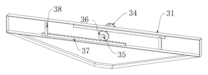
Applications
High-volume ball valve production
Ideal for factories producing thousands of identical valves daily, where cycle time reduction directly impacts profitability.
Precision aerospace or medical valves
Suitable for applications requiring exact seating depth and uniform pressure distribution to prevent leakage under extreme conditions.
Automated assembly lines
Integrates easily into existing conveyor systems as a standalone station for the seat-fitting process, replacing manual presses.
Custom valve prototyping
Allows engineers to test different seat materials and thread designs quickly without building custom hand tools for each iteration.
Where it is less suitable
- Very large industrial valves: The physical size of the fixture may be constrained by standard workshop limits; larger valves may need heavier-duty frames.
- Non-standard geometries: Designed specifically for the described hemispherical cavity and threaded seat structure; irregular valve shapes would require significant redesign.
- Low-volume bespoke work: The setup complexity outweighs benefits if only a few unique valves are made per batch.
Patent & Production
At a glance
| Patent number | CN118149126B (application CN202410565348) |
| Type | China invention patent (发明专利) - protects method and apparatus |
| Original title | A valve and its valve seat fastening tooling (一种阀门及其阀座紧固工装) |
| Patent owner | Weilong Valve Co ltd |
| Inventors | Zhang Huifang, Guo Fengtian |
| Filing date | 2024-05-09 |
| Grant date | 2024-08-02 |
| Status (China) | In force - valid until at most 2044-05-09, provided annual fees are paid |
| Patent family | Public record shows Chinese filings only - no US, European, Japanese, PCT or other filings listed |
| Cited by | 0 later documents |
| Source | Google Patents (search for CN118149126B) |
What the claims cover, in plain language
Claim 1 - defines a valve seat fastening tooling comprising a tool rack equipped with valve seat limiting discs and valve rod limiting discs. The system interacts with a specific valve structure featuring a hemispherical sealing cavity and locking internal/external threads. Key mechanical features include a circular ring blocking block formed at channel intersections, hollow circular table blocks for guiding seats, and a double-end screw rod for manual adjustment. The automation aspect involves a driving mechanism with a first driving motor linked to a driving gear and two driven racks to move the limiting discs symmetrically. A rotating half gear and vertical rack manage the valve rod position. Additionally, magnetic blocks (fixed and movable) within a sliding rail control the retraction of limiting arc blocks. A second driving motor powers rotary telescopic rods to screw the seats into place.
This is a simplified reading for orientation only. The legal scope is defined by the exact claim wording in the official Chinese document.
What this means for US production
This patent was filed in China and is currently in force. The public record shows no US or other foreign counterpart. Therefore, making or selling this specific fixture design in China requires the owner’s permission. However, because there is no US patent family member, the design itself does not restrict manufacture or sale in the United States based on this document alone.
Two points to settle early:
- Other patents may exist. Industrial automation fixtures and valve assembly tools are a competitive field. While this specific combination of magnetic sliders and half-gears appears unique to this filing, prior art in pneumatic or hydraulic valve assembly should be reviewed. A freedom-to-operate (FTO) review is recommended before mass production to ensure no other US patents cover similar automated seating mechanisms.
- Integration complexity. This is a complex electromechanical device. Replicating it requires sourcing specific motors, custom-machined racks, and precisely aligned magnetic rails. Small deviations in gear ratios or magnet strength could affect the synchronization described in the patent.
Customization and manufacturing
What can be customized
| Area | Options |
|---|---|
| Valve Size | Adapted for different diameter valve bodies and seat lengths |
| Drive Type | Electric motors (as patented) or pneumatic cylinders for air-powered shops |
| Material | Aluminum frame vs. steel frame for weight and rigidity balance |
| Control System | PLC integration for automated line connectivity |
| Fixtures | Quick-change clamps for varying valve models |
Things to plan for (US market)
- OSHA Machine Guarding: Moving gears, racks, and telescopic rods must be enclosed to prevent pinch-point injuries.
- Electrical Safety (UL/NFPA 79): If electric motors are used, the control panel and wiring must meet National Electrical Code standards for industrial machinery.
- CE Marking (for export): If selling to Europe, additional safety directives apply.
How a project runs
- Inquiry - specify valve dimensions, target cycle time, and integration needs.
- Design - CAD modeling of the rack-and-pinion system and magnetic slider layout.
- Prototype - build functional unit using machined parts and off-the-shelf motors.
- Testing - verify synchronization of dual-seat insertion and torque accuracy.
- Production - fabricate frames, assemble drives, install guards, and program controls.
Quantities & timeline
Tooling involves machining the L-shaped rod bodies, cutting the rack teeth, and assembling the magnetic rails. Lead times depend heavily on the availability of custom-cut gears and high-grade magnets. Send us your valve specifications, desired cycle rate, and factory environment details and we will reply with options.
Production notes
Tooling and process
Likely involves machining for the aluminum or steel frames to ensure tight tolerances on the sliding rails. Gears and racks typically require hobbing or shaping processes. Injection molding might be used for plastic protective covers or handles.
Cost drivers
Cutting edge machining for the rack teeth likely adds cost. Assembly steps are typically numerous because of the magnet and sensor alignment. Surface finish requirements for the sliding interfaces influence material selection and processing time.
Prototyping path
Start with a 3D-printed handle or jig to test ergonomics. Machined or off-the-shelf equivalents are typically used for the initial gear tests. Functional samples should verify the magnetic retention strength before full tooling.
What we would change before tooling
We would likely simplify the half-gear mechanism if intermittent motion proves difficult to tune. Shaft and bearing alignment tolerances would typically be verified to prevent premature wear in high-cycle environments.
Common failure points
Pivot pin wear is likely in the telescopic rod joints. Magnet grade and retention must be checked to avoid slipping during heavy pressing. Thread engagement issues can arise if the rotary rods are not perfectly aligned with the valve body.
Patent drawings
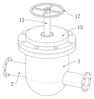
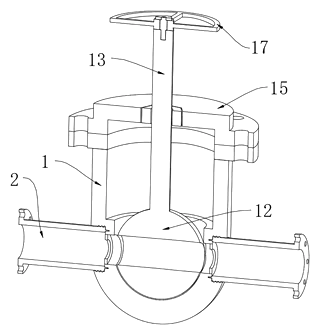
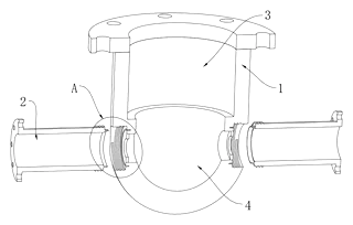
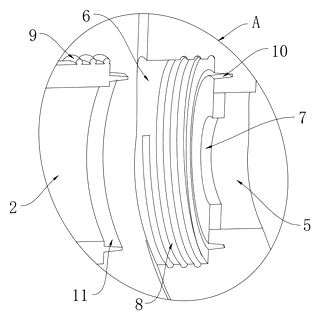
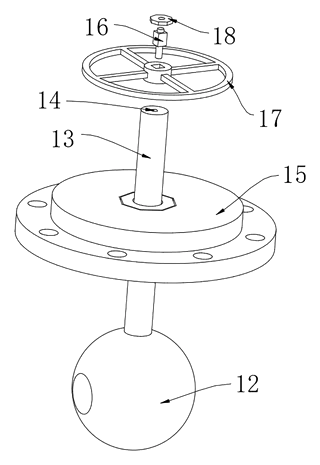
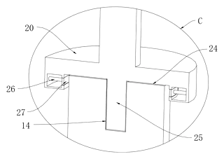
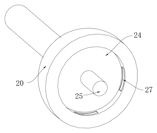
Drawings reproduced from the public patent document for reference.
Frequently asked questions
How does the fixture synchronize the two seats?
It uses a single central driving gear connected to two separate racks. When the motor turns the gear, both racks move inward at the same speed and distance, pushing the two valve seats into the body simultaneously.
Why use magnets instead of springs for the sliders?
The patent specifies fixed and movable magnets with opposite poles attracting each other. This allows for a smooth, controlled retraction of the limiting arc blocks without the fatigue or inconsistency that springs might introduce over thousands of cycles.
Can it handle different valve sizes?
Yes, but it requires customization. The spacing of the racks, the length of the telescopic rods, and the shape of the limiting blocks must be adjusted to match the specific diameter and depth of the valve body you are producing.
Is the screwing action automatic?
Yes. After the seats are pressed into place, a second motor engages rotary telescopic rods. These rods grip the seats and rotate them to thread the external locks into the internal channels, completing the assembly without manual wrenching.
What happens if the valve rod is misaligned?
The system includes a vertical rack driven by a half-gear. This mechanism lowers the valve rod into its correct position before the seats are inserted. If alignment fails, the sensors (implied by the motor control logic) would stop the cycle to prevent jamming.
Do I need special training to operate it?
Operators need basic understanding of the start/stop sequence and emergency stops. Since it is an automated fixture, most tasks are handled by the motors, reducing the skill level required compared to manual assembly.
Can this design be made and sold in the US?
The patent was filed in China and is currently in force there. However, the public record shows no US counterpart. Therefore, this specific design does not restrict manufacturing or sales in the US. We still recommend a freedom-to-operate check to ensure no other US patents cover similar automated valve assembly techniques.
Are you affiliated with the patent owner?
No. IP2M is an independent design and manufacturing service working from the public patent document.
Request a quote
Click Request a Quote below to see our email address - copy it, or open your email app with a ready-made message. Please mention patent CN118149126B in the subject.
Helpful details to include:
- Your company and channel (valve manufacturer, automation integrator, OEM)
- Valve dimensions (body diameter, seat length, thread pitch)
- Target cycle time (seconds per unit)
- Factory environment (space constraints, power supply, network protocols)
- Estimated quantity of fixtures needed
- Timeline - when you would like prototypes and the first shipment
You can also reach us at (332) 203-9997.
Page editor: Emily Zhang, Product Editor · IP2M
Last updated November 8, 2026. If something on this page looks wrong, email [email protected] and we will check it against the patent.
Interested in building this?
Tell us your target market, quantity and timeline. We reply with options for prototyping, small-batch runs or volume production.
Send your inquiry to
Please put CN118149126B in the subject line and tell us your company, country, estimated quantity and timeline.
Prefer to talk? Call (332) 203-9997.
More product-ready patents
All Tools & Workshop patents →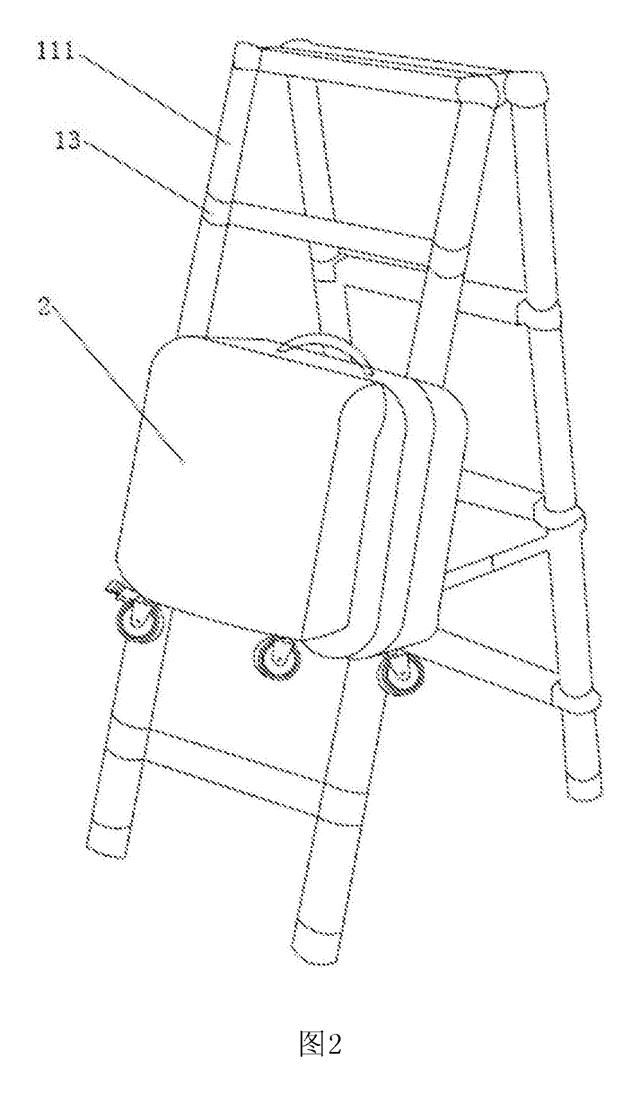
Tools & Workshop
Rolling Tool Box with Telescoping Step Ladder
Telescoping A-frame ladder with an attached rolling tool box that slides to your working height.
Patent CN206290197U
Tools & Workshop
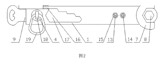
Folding 3-Handle Wrench Multi-Tool
Folding three-handle wrench multi-tool with magnetic screwdriver bits, saw, file and bottle opener.
Patent CN205290875U
Tools & Workshop
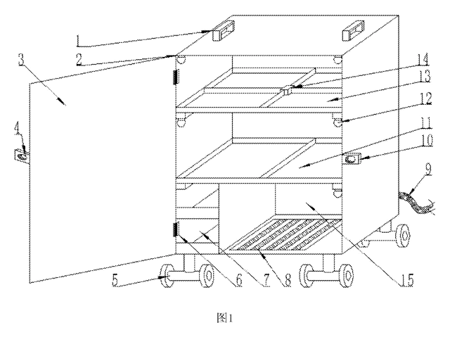
Rolling Auto-Repair Tool Cabinet with Built-In Lights
Lockable rolling tool cabinet for car repair with interior lights, a lubricant tray, parts drawers and a tool bay.
Patent CN205989314U
Tools & Workshop
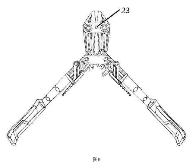
Wide-Opening Folding Bolt Cutter
Bolt cutter with linked, gear-meshing handles that open up to 190° and fold in half for storage.
Patent CN207206226U
Tools & Workshop
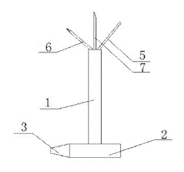
Nail-Holding Hammer with Fold-Out Drivers
Hammer with a nail-holding T-slot in the head and fold-out drivers stored in the handle.
Patent CN205254927U
Tools & Workshop
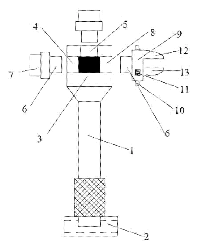
Modular Wrench with Screw-On Heads
Wrench handle with a three-way threaded hub for screw-on adjustable and hex heads, plus a pipe sleeve.
Patent CN206216564U
Browse by category
- Apparel & Accessories (50)
- Baby & Kids (29)
- Bags & Luggage (17)
- Bath & Personal Care (33)
- Car Accessories (26)
- Furniture, Bedding & Storage (25)
- Garden & Outdoor (34)
- Health & Wellness (14)
- Home, Kitchen & Cleaning (52)
- Lighting (24)
- Packaging & Containers (13)
- Pet Products (12)
- Phone & Camera Accessories (9)
- Retail Display (26)
- School, Office & Art (38)
- Sports & Recreation (48)
- Tools & Workshop (56)
- Toys & Games (23)
This page is based on the public patent document CN118149126B, assigned to Weilong Valve Co ltd. IP2M is an independent manufacturing service and is not affiliated with, endorsed by or licensed by the patent owner. Images marked as concept renderings are illustrations, not photos of an existing product. Patent status information is provided for reference only and is not legal advice; confirm freedom to operate for your market before production. Full disclaimer.