
Patent CN118328254B
Updated October 29, 2026Remote-Controlled Outdoor Photography Tripod with Movable Lens Mount
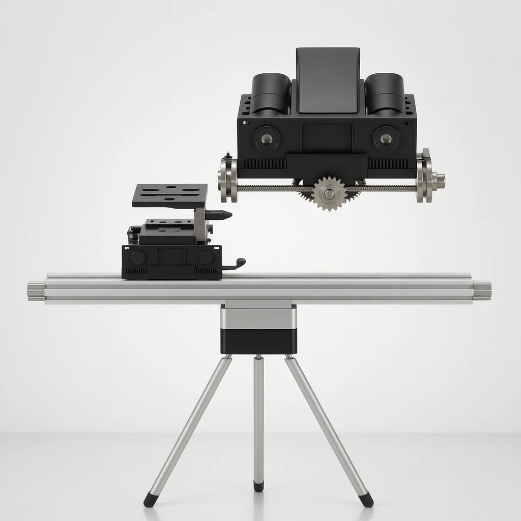
Outdoor photographers often need to track moving subjects across a wide area while adapting to changing light by switching lenses. Doing both manually requires constant physical adjustments that can shake the setup or cause missed shots. This tripod design addresses that workflow by combining a motorized camera seat with a sliding multi-lens carriage on a single platform. The camera seat moves along the Y-axis of the mounting platform in response to remote commands sent via a handheld controller or a mobile phone application. As the camera tracks a subject, a mechanical gear linkage keeps the lens seat moving in step so the active lens stays aligned. If a different lens is needed, the mechanism allows the lens seat to shift relative to the camera seat, bringing another pre-mounted lens into position without manual intervention. A mechanical cover system protects the unused lenses and opens automatically only when the camera is correctly aligned, using an abutting rod to trigger a rack-and-gear rotation.
- China invention patent - in force
- No filings outside China
- Photography & video equipment
- Motorized tracking, gear-driven lens switching
Splat! What let you down?
📡
Remote tracking
A driving device receives remote instructions to move the camera seat along the platform for follow-up shooting.
🔭
Sliding lens mount
A lens seat holds multiple lenses and moves synchronously with the camera or shifts independently to change lenses.
⚙️
Gear synchronization
Two lead screws, a first gear and a second gear meshing with a toothed structure coordinate the camera and lens movements.
🛡️
Automatic lens cover
A protective cover opens mechanically via an abutting rod and rack when the camera aligns with a lens hole.
Bring this product to market
- ✓ Patent vetted China-only family and legal status checked
- 2 Product brief · now How it works, uses and options written up
- 3 Prototype First samples for buyers to review
- 4 Pilot run Small first batch for launch customers
- 5 Volume production Repeat orders at scale
Buyer interest
– of 100 buyers needed to start prototyping
One click, no sign-up. Each vote is one real visitor, and products with the most interest go to prototyping first.
Build team: no members yet. Need a partner, co-funding or skills to build this? Join and we introduce the team once it forms.
The problem
When shooting outdoors, photographers frequently need to track moving subjects such as wildlife, athletes or vehicles. Tracking requires panning the camera smoothly while keeping the subject framed. At the same time, changing outdoor lighting conditions—such as shifting from morning sun to midday glare or overcast shadows—often require swapping lenses. On a standard tripod, both actions demand manual handling. Touching the camera to change a lens interrupts tracking, risks shaking the frame, and exposes the sensor and glass elements to dust and weather. Motorized pan heads exist, but they typically move only the camera, leaving lens changes entirely to the operator’s hands.
The solution
This tripod integrates a motorized tracking system with a mechanical lens-switching carriage on a single mounting platform.
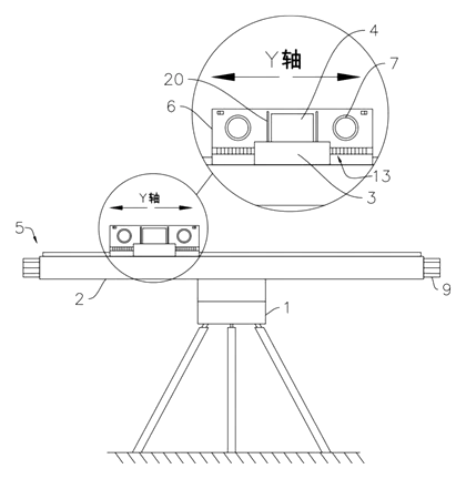
- A frame body (1) supports a mounting platform (2) shaped as a sliding table, providing a Y-axis direction for movement.
- A mounting seat (3) moves along the platform, carrying a camera (4).
- A driving device (5) on the platform receives remote instructions to push the mounting seat along the Y-axis, allowing the camera to follow a moving object.
- A lens seat (6) also moves on the platform, holding several lenses (7) in a row along the moving direction.
- The driving device uses two side-by-side lead screws (8) turned by driving pieces (9), linked by a first gear (10). A connecting shaft (11) on the first gear attaches to the mounting seat.
- A second gear (12) on the connecting shaft meshes with a toothed structure (13) on the side wall of the lens seat. When the mounting seat moves, the gears keep the lens seat traveling in step. When the second gear rotates independently, it shifts the lens seat relative to the camera to align a different lens.
Who it is for
- Photography equipment brands looking to add a motorized, multi-lens tracking tripod to their outdoor gear catalog.
- Wildlife and nature videographers who need to follow animals across a distance without physically touching the rig to swap glass.
- Sports and event production crews filming outdoor matches where lighting shifts quickly and subjects move fast across the field.
- Amazon sellers and wholesalers sourcing specialized camera mounts for content creators who shoot solo outdoors.
How it works
The main parts
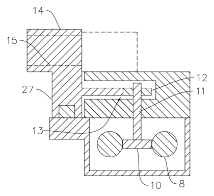
| No. | Part | What it does |
|---|---|---|
| 1 | Frame body | Supports the entire assembly. |
| 2 | Mounting platform | Sliding table providing the Y-axis path. |
| 3 | Mounting seat | Carries the camera and moves along the platform. |
| 4 | Camera | Mounted on the seat for shooting. |
| 5 | Driving device | Receives remote instructions to move the mounting seat. |
| 6 | Lens seat | Holds multiple lenses; includes a mounting portion (14) and transfer unit (27). |
| 7 | Lenses | Placed in mounting holes (15) along the moving direction. |
| 8 | Lead screws | Two side-by-side screws transmitting motion. |
| 9 | Driving pieces | Connected to the lead screws to turn them. |
| 10 | First gear | Meshes between the two lead screws. |
| 11 | Connecting shaft | On the first gear; links to the mounting seat. |
| 12 | Second gear | On the connecting shaft; meshes with the toothed structure. |
| 13 | Toothed structure | On the side wall of the lens seat. |
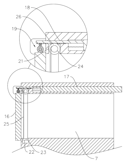
| 16 | Protective cover | Covers the mounting holes; rotates open via a driving gear (19). |
| 20 | Abutting rod | On the mounting seat; pushes the driving rack (18) to open the cover. |
| 22 | Cleaning rods | Slide between storage grooves (21) with cleaning pieces (23). |
Operating steps
- Send a remote instruction via a controller or mobile phone APP. The driving device turns the lead screws, moving the mounting seat and camera along the Y-axis to track a subject.
- Synchronized travel: As the mounting seat moves, the first gear turns the connecting shaft. The second gear on this shaft rolls against the toothed structure, pulling the lens seat along at the same pace so the active lens stays aligned with the camera.
- Switching lenses: To change the lens, the second gear rotates to push the lens seat relative to the mounting seat. A different mounting hole aligns with the camera.
- Opening the cover: When alignment is reached, the abutting rod on the mounting seat pushes the driving rack inside the connecting hole. The rack turns the driving gear on the protective cover’s shaft, rotating the cover open to expose the selected lens.
Applications
Wildlife tracking
Nature photographers following animals across open terrain can use the remote drive to pan the camera smoothly. The lens seat moves in step, keeping the telephoto lens aligned without the operator walking alongside the rig.
Sports field recording
Videographers filming outdoor matches can track players running down the field. When lighting changes from direct sun to stadium shadows, the mechanism shifts the lens seat to bring a faster lens into position remotely.
Solo landscape and time-lapse work
Solo shooters setting up time-lapses in changing weather can leave the tripod running. If the sequence requires a wider or narrower field of view, the remote command switches the lens mechanically while the platform continues its programmed movement.
Educational and club demonstrations
Photography instructors teaching outdoor classes can demonstrate lens changes and tracking simultaneously. Students observe the mechanical coordination without crowding around the tripod to manually twist lens barrels.
Where it is less suitable
- Indoor studio tabletop photography - the Y-axis sliding table and heavy frame body are built for outdoor ground placement, not small studio desks.
- Handheld gimbal use - this is a stationary tripod system; it cannot be carried while walking.
- Single fixed-lens setups - if a user never swaps lenses, the multi-hole lens seat and gear synchronization add unnecessary complexity compared to a basic pan head.
Frequently asked questions
How does the camera follow a moving subject?
The driving device receives a remote instruction and turns two side-by-side lead screws. These screws push the mounting seat along the Y-axis of the sliding platform, moving the camera to track the object.
How are lenses switched without touching the camera?
A lens seat holds multiple lenses in a row. A second gear on the connecting shaft meshes with a toothed structure on the lens seat. Rotating this gear shifts the lens seat relative to the camera seat, bringing a different lens hole into alignment.
Do the camera and lenses always move together?
When tracking a subject, the gear linkage keeps the lens seat moving synchronously with the mounting seat so the active lens stays in front of the camera. They only move relative to each other when a lens change is commanded.
What powers the driving device?
The patent describes driving pieces connected to the lead screws and receiving remote instructions via a controller or mobile phone app. The specific motor type and battery details are set in design and confirmed on prototypes.
How does the protective cover open?
An abutting rod on the mounting seat pushes a driving rack inside a connecting hole when the camera aligns with a lens. The rack turns a driving gear on the cover’s shaft, rotating the cover open to expose the lens.
Can it handle heavy cinema cameras?
The patent does not specify weight limits. The load capacity depends on the lead screw diameter, motor torque and platform materials, which are set in design and confirmed on prototypes based on the buyer’s camera specifications.
Does it include automatic subject detection?
The patent mentions that locking onto a subject can be done manually via remote operation or through a sensing system arranged on the frame body to identify and lock the object, potentially cooperating with an AI module. These electronic features are configured during product development.
Can this design be made and sold in the US?
The patent was filed only in China and is in force in China until at most 2044-06-12 (if annual fees are paid). It does not restrict making or selling the design in the US. However, motorized camera mounts may be covered by other US patents - see Patent & Production - so we recommend a freedom-to-operate check before volume production.
Are you affiliated with the patent owner?
No. IP2M is an independent design and manufacturing service working from the public patent document.
Request a quote
Click Request a Quote below to see our email address - copy it, or open your email app with a ready-made message. Please mention patent CN118328254B in the subject.
Helpful details to include:
- Your company and channel (photography brand, Amazon seller, wholesale distributor, production rental house)
- Target camera payload and lens diameters
- Required Y-axis travel distance
- Control method (remote controller, mobile app, or both)
- Estimated quantity and target price
- Timeline - when you would like samples and the first shipment
You can also reach us at (332) 203-9997.
Explore this product
Interested in building this?
Tell us your target market, quantity and timeline. We reply with options for prototyping, small-batch runs or volume production.
Send your inquiry to
Please put CN118328254B in the subject line and tell us your company, country, estimated quantity and timeline.
Prefer to talk? Call (332) 203-9997.
More product-ready patents
All Phone & Camera Accessories patents →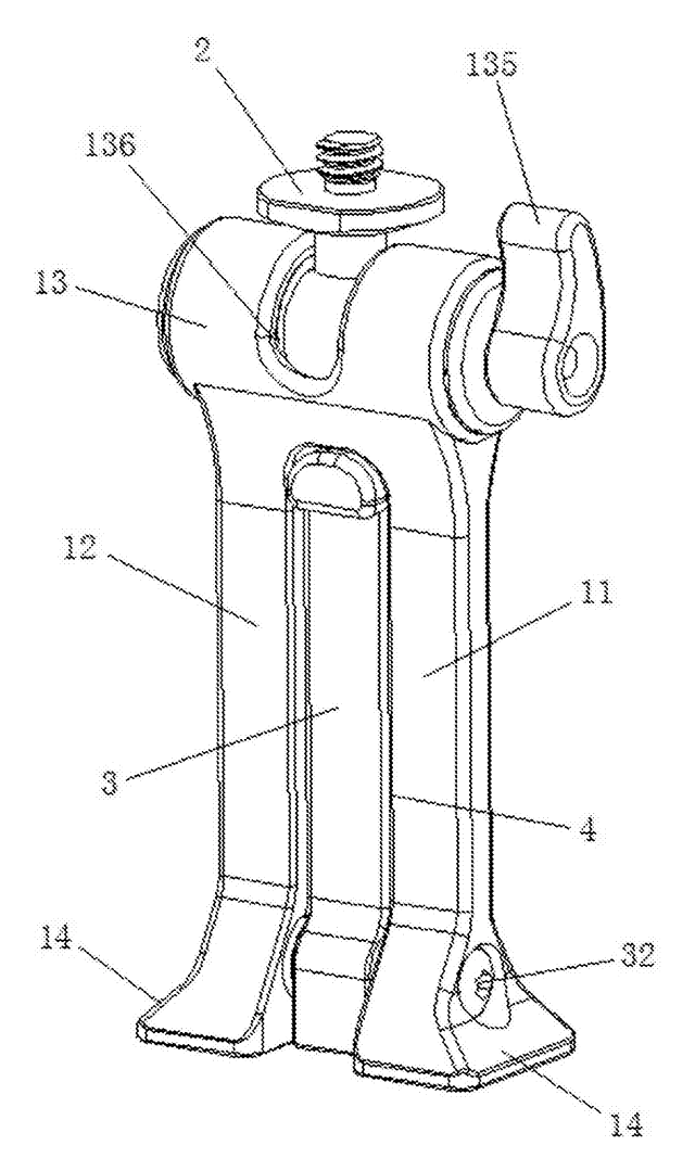
Phone & Camera Accessories
Phone Clip Mount with Fold-Out Stand Leg
Phone clamp adapter with a ball-joint top, a dovetail base for tripod clamps and a fold-out desk leg.
Patent CN207394276U
Stands & Mounts
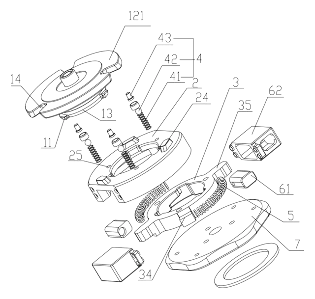
Manual Quick-Release Connector for Camera Equipment
Quick-release camera mount using a rotating driver and spring-loaded locking grooves.
Patent CN215294199U
Phone & Camera Accessories
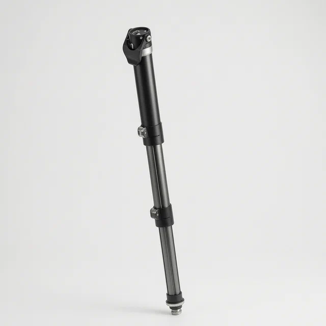
Extendable Support Leg and Monopod with Single-Knob Locking
Three-section monopod leg locked and released from one top knob via a transmission rod.
Patent CN113090903B
Sports & Recreation
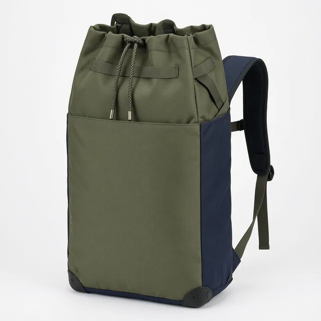
Multifunctional Outdoor Backpack with Built-In Rest Stool and Emergency Stretcher
Field backpack converting into a rest stool, stretcher or wheeled cart via internal frame parts.
Patent CN107087887B
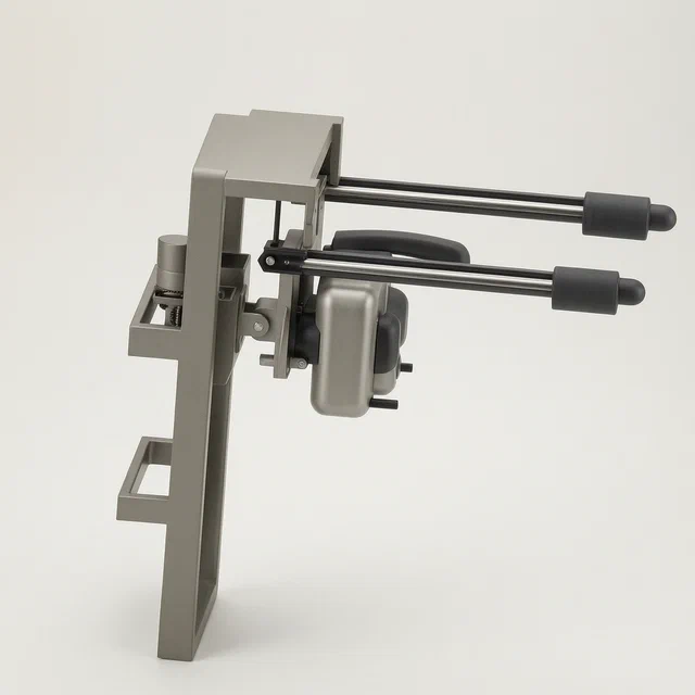
Health & Wellness
Wall-Mounted Massager with Motorized Lifting and Auto-Folding Armrest
Wall-mounted massager: motorized vertical lift and an armrest that auto-folds at the top.
Patent CN108514507B
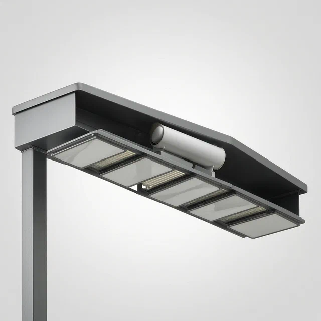
Lighting
Street Lamp Angle Adjusting Mechanism with Rotatable Reflectors
Street lamp mechanism tilts the housing and pivots reflectors to aim light at narrow roads.
Patent CN118564871B
Browse by category
- Apparel & Accessories (22)
- Baby & Kids (16)
- Bags & Luggage (9)
- Bath & Personal Care (16)
- Car Accessories (10)
- Furniture, Bedding & Storage (12)
- Garden & Outdoor (18)
- Health & Wellness (8)
- Home, Kitchen & Cleaning (24)
- Lighting (12)
- Packaging & Containers (6)
- Pet Products (6)
- Phone & Camera Accessories (4)
- Retail Display (13)
- School, Office & Art (19)
- Sports & Recreation (25)
- Tools & Workshop (27)
- Toys & Games (12)
This page is based on the public patent document CN118328254B, assigned to Sichuan Aviation Vocational College Sichuan Space Advanced Technical School. IP2M is an independent manufacturing service and is not affiliated with, endorsed by or licensed by the patent owner. Images marked as concept renderings are illustrations, not photos of an existing product. Patent status information is provided for reference only and is not legal advice; confirm freedom to operate for your market before production. Full disclaimer.