At a glance
| Patent number | CN118328254B (application CN202410750054) |
| Type | China invention patent (发明专利) - protects product shape, structure and method |
| Original title | Intelligent tripod for outdoor photography (一种户外摄影用智能型三脚架) |
| Patent owner | Sichuan Aviation Vocational College Sichuan Space Advanced Technical School |
| Inventors | Yang Jin, Deng Fei |
| Filing date | 2024-06-12 |
| Grant date | 2024-08-16 |
| Status (China) | In force in China until at most 2044-06-12 (if annual fees are paid) |
| Patent family | Chinese filings only - no US, European, Japanese, PCT or other filings listed |
| Cited by | 0 later documents |
| Source | Google Patents (search for CN118328254B) |
What the claims cover, in plain language
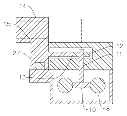
Claim 1 - an intelligent tripod comprising a frame body with a mounting platform at the top. A mounting seat moves on the platform and carries a camera. A driving device on the platform receives a remote instruction to move the mounting seat. A lens seat also moves on the frame body, holding several lenses along the moving direction. The lens seat moves with the mounting seat to keep their relative position, or moves relative to it to align a different lens. The driving device has a screw rod connected to a driving piece; two groups are side by side, meshed by a first gear. A connecting shaft on the first gear connects to the mounting seat and carries a second gear that meshes with a toothed structure on the lens seat. Moving the mounting seat causes the second gear to abut the toothed structure for synchronous travel; rotating the second gear stirs the toothed structure for relative movement.
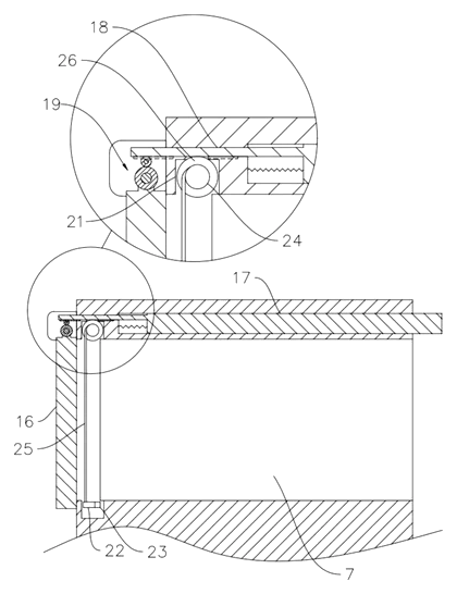
Claim 2 - the remote instruction is sent by a remote controller or a mobile phone APP. Claim 3 - the lens seat has a mounting portion with mounting holes for the lenses, and a protective cover on the side facing away from the camera, which opens after detecting relative signals of the camera and lens. Claim 4 - the protective cover rotates on the mounting part; a connecting hole holds a spring-loaded driving rack that meshes with a driving gear on the cover’s shaft. An abutting rod on the mounting seat pushes the rack to rotate the cover open when the camera faces a mounting hole. Claim 5 - storage grooves above and below the lens hold cleaning rods with cleaning pieces, operated by winding rollers in the upper grooves.
This is a simplified reading for orientation only. The legal scope is defined by the exact claim wording in the official Chinese document.
What this means for US production
This patent was filed only in China and is currently in force in China until at most 2044-06-12 (if annual fees are paid). It has no US or other foreign counterpart. However, making or selling this specific tripod design in China needs the owner’s permission while the patent remains in force.
Two points to settle early:
- Other patents may exist. Motorized camera sliders, electronic pan-tilt heads and automated lens changers are active areas of development among major camera accessory makers. Because no foreign patents cite this Chinese filing, there are no specific later US holders identified here, but a freedom-to-operate (FTO) review covering motorized tracking platforms and gear-driven lens carousels is recommended before tooling.
- Electronic control integration. The patent describes remote instructions via an app or controller and mentions optional AI modules or sensing systems. Integrating these electronics requires selecting motors, controllers and wireless modules that fit the mechanical gear ratios described in the claims.
Customization and manufacturing
What can be customized
| Area | Options |
|---|---|
| Platform travel | Length of the Y-axis sliding table to be confirmed in design |
| Load capacity | Sized for mirrorless or cinema cameras by adjusting lead screw pitch and motor torque |
| Lens mount holes | Number and spacing of holes set in design based on target lens diameters |
| Materials | Frame body and platform in aluminum alloy or steel; gears in POM or metal |
| Electronics | Choice of stepper or servo motors, Bluetooth/Wi-Fi modules for app control |
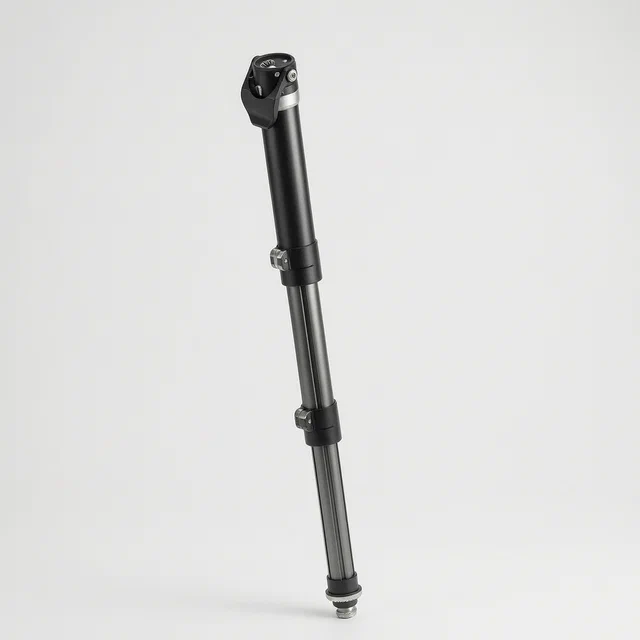
| Tripod legs | Standard telescoping legs or custom carbon-fiber tubes attached to the frame body |
Things to plan for (US market)
- FCC Part 15 - if the driving device or controller uses wireless communication (Bluetooth, Wi-Fi) to receive remote instructions, the radio module must comply with FCC rules.
- California Prop 65 - materials used in the frame, gears and covers must be screened for listed substances.
- UN 38.3 and UL 2054 - only if the driving device is powered by a lithium battery pack; the patent does not specify the power source, so this is set in design.
How a project runs
- Inquiry - define the camera payload, lens sizes, travel distance and control method.
- Design - engineer the lead screws, gear ratios, mounting seat and lens seat profiles, plus the cover mechanism.
- Prototype - machine samples to verify smooth Y-axis travel, gear synchronization and cover actuation.
- Pilot run - test the remote app communication, motor heat under continuous tracking, and mechanical wear on the toothed structure.
- Production - CNC machining or die casting for the frame and seats, gear cutting or molding, electronic assembly and final calibration.
Quantities & timeline
The frame body and mounting platform require CNC machining or casting dies sized for the chosen travel length. Lead screws, gears and the toothed structure need precision machining or injection molds depending on the material. Electronic components such as motors, controllers and wireless modules are sourced separately and integrated during assembly. Certification tests for FCC and UL add to the schedule. Send us your payload requirements, lens dimensions, travel length, control preferences, quantity and target price and we will reply with options.
Patent drawings
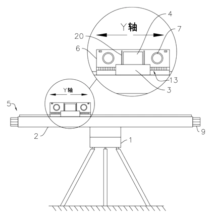
Drawings reproduced from the public patent document for reference.