
Patent CN118405064B
Updated November 1, 2026Automobile Luggage Rack with Automatic Alignment and Quick-Release Clamping
Installing traditional roof racks often requires precise manual alignment of crossbars against mounting points, which can be difficult when working alone or in poor lighting. This design solves that by using a mechanical linkage triggered simply by placing the crossbeam onto the rail. As the beam slides into the clamp groove, internal gears and springs drive the clamping blocks inward, automatically centering the assembly. Once centered, a locking mechanism secures the position, eliminating the need for repeated manual adjustments and ensuring consistent placement every time.
- China invention patent - active
- No filings outside China
- Automotive accessories
- Mechanical linkage & spring-driven alignment
Splat! What let you down?
🚗
Auto-Centering
Insertion of the crossbeam triggers a linkage that pushes it to the middle position automatically.
⚙️
Spring-Driven Linkage
Uses stored energy in a spring-loaded disc and rotating rods to drive the clamping screws.
🔒
Secure Locking
Clamping blocks move oppositely to grip the longitudinal beam firmly once aligned.
🛠️
Tool-Free Installation
Eliminates manual alignment steps, reducing installation time and labor intensity.
Bring this product to market
- ✓ Patent vetted China-only family and legal status checked
- 2 Product brief · now How it works, uses and options written up
- 3 Prototype First samples for buyers to review
- 4 Pilot run Small first batch for launch customers
- 5 Volume production Repeat orders at scale
Buyer interest
– of 100 buyers needed to start prototyping
One click, no sign-up. Each vote is one real visitor, and products with the most interest go to prototyping first.
Build team: no members yet. Need a partner, co-funding or skills to build this? Join and we introduce the team once it forms.
The problem
Traditional roof rack installations often require users to manually align crossbars with specific mounting points on the vehicle’s longitudinal rails. This process can be cumbersome, especially when installing alone, as holding the heavy crossbar steady while adjusting its position is physically demanding. Misalignment leads to uneven load distribution and potential instability. Furthermore, securing the bars typically involves tightening multiple bolts or knobs individually, which adds complexity and time to the setup process. Users frequently struggle to achieve a perfectly centered look without repeated adjustments.
The solution
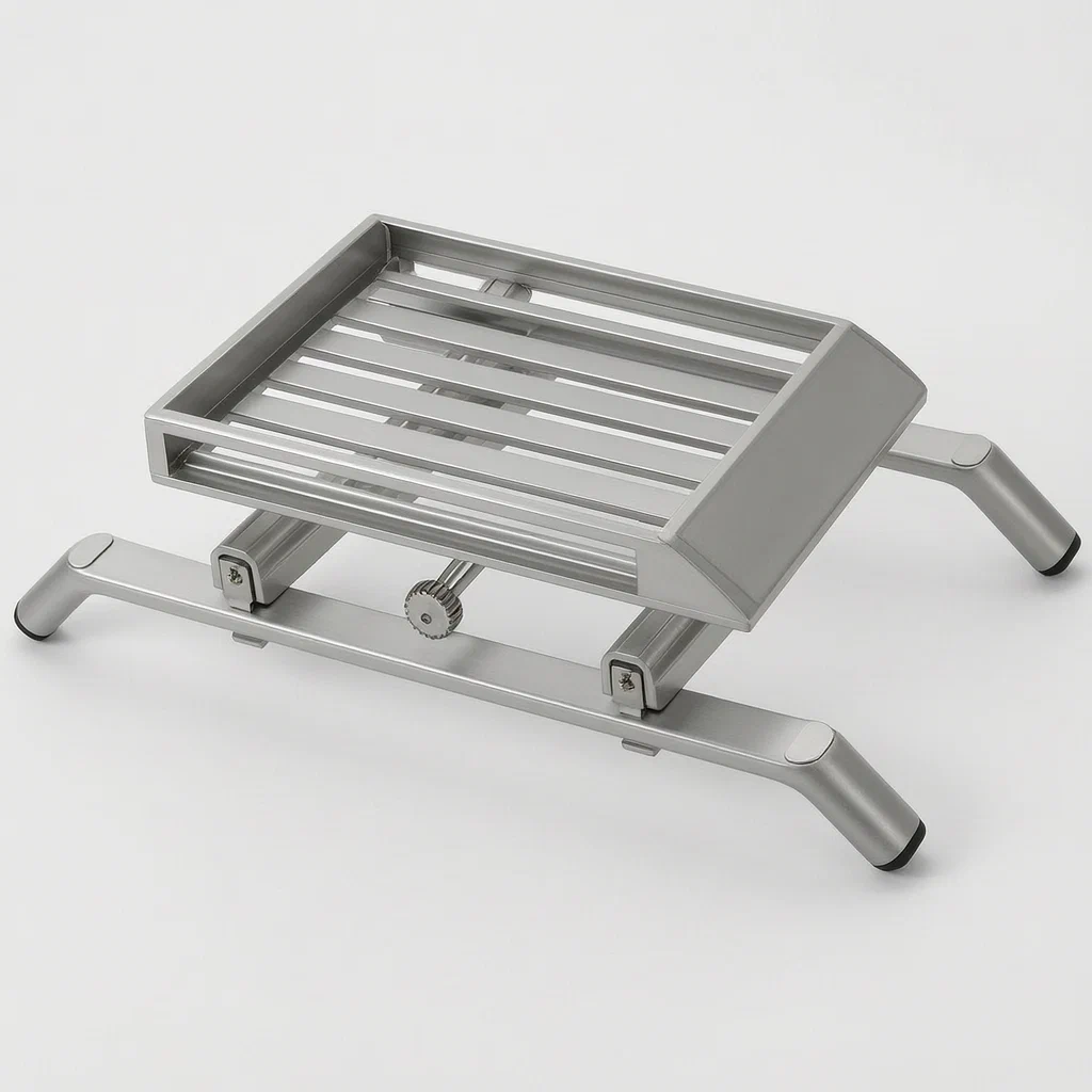
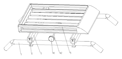
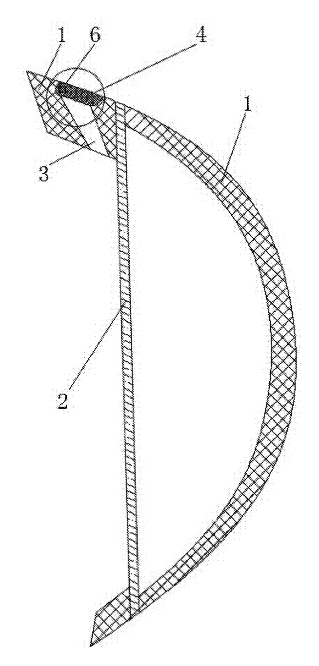
This design introduces a mechanical system that automates the alignment and initial clamping phase. It consists of two longitudinal beams mounted on the car roof and two crossbeams installed perpendicularly on top of them. A reinforcing plate connects the crossbeams. The key innovation lies in the connection between the crossbeam ends and the longitudinal beams. Each crossbeam end features a sliding slot containing a cassette (clamp seat). Inside this cassette, a linkage mechanism is activated by the simple act of placing the crossbeam onto the longitudinal beam.
- Placement: The user places the crossbeam onto the longitudinal beam.
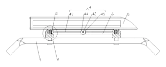
- Activation: The longitudinal beam enters the clamping groove of the cassette. This physical insertion drives an input rod within the linkage mechanism.
- Energy Transfer: The movement rotates a first gear connected to a rack on the input rod. This rotation drives a power storage disc (spring-loaded) and a transmission mechanism.
- Automatic Centering: The linkage forces the clamping blocks to move inward from both sides toward the center of the longitudinal beam. This reaction force pushes the entire crossbeam assembly smoothly to the middle position of the rails.
- Locking: Once centered, the locking mechanism engages, securing the crossbeam firmly against the longitudinal beam without further manual adjustment.
Who it is for
- Aftermarket Automotive Brands looking to differentiate their roof rack products with ease-of-use features.
- Outdoor Equipment Retailers selling to consumers who value quick setup for camping trips and sports gear transport.
- Vehicle Fleet Managers needing efficient loading/unloading procedures for utility vehicles.
- DIY Enthusiasts who prefer tool-free or minimal-tool installation processes for vehicle modifications.
How it works
The main parts
| No. | Part | What it does |
|---|---|---|
| 1 | Longitudinal Beam | Mounted on the car roof; serves as the base track. |
| 2 | Crossbeam | Runs perpendicular to the longitudinal beam; carries cargo. |
| 3 | Cassette (Clamp Seat) | Slides inside the crossbeam slot; grips the longitudinal beam. |
| 4 | Linkage Mechanism | Converts insertion motion into rotational force via gears and springs. |
| 5 | Power Storage Disc | Spring-loaded component that stores and releases energy for movement. |
| 6 | Screw Rod & Clamp Block | Moves linearly to tighten against the longitudinal beam profile. |
| 7 | Reinforcing Plate | Connects the two crossbeams for structural stability. |
Operating Steps
- Mount Longitudinal Beams: Install the base rails on the vehicle roof according to standard procedures.
- Place Crossbeam: Lift the crossbeam assembly and place it over the longitudinal beams.
- Trigger Linkage: As the longitudinal beam slides into the cassette’s clamping groove, it pushes the input rod.
- Drive Gears: The input rod moves a rack, rotating the first gear and driving the spring-loaded power storage disc.
- Center Assembly: The transmission mechanism converts this rotation into linear motion, pushing the clamp blocks inward. The equal opposing force centers the crossbeam automatically.
- Secure: The locking mechanism holds the position, completing the installation.
Applications
Camping and Overlanding
Travelers can quickly attach cargo boxes or kayaks before departure. The auto-centering ensures balanced weight distribution, preventing one side of the vehicle from bearing more load than the other during rough terrain driving.
Sports Gear Transport
Skiers and surfers often install racks seasonally. This system allows for rapid deployment in parking lots without fumbling with loose bolts in cold or wet conditions, making it easier to mount boards and skis securely.
Urban Delivery Fleets
Couriers using motorcycles or small vans need to swap out attachments frequently. The quick-release nature reduces downtime between deliveries, allowing drivers to adjust their cargo configuration efficiently throughout the day.
Vehicle Rental Services
Rental companies offer optional roof racks. Customers appreciate the simplicity of setting up their own equipment without needing assistance from staff, reducing liability and improving customer satisfaction scores.
Where it is less suitable
- Heavy Industrial Loads: For extremely heavy machinery or specialized industrial transport, rigid bolted connections may still be preferred for maximum security.
- Fixed Permanent Racks: If the rack is never removed, the complexity of the linkage mechanism offers no advantage over simpler fixed brackets.
- Non-Standard Rail Profiles: Vehicles with unique or irregular roof rail shapes may not accommodate the standard clamping groove dimensions described in the patent.
Frequently asked questions
How does the auto-centering work?
When you place the crossbeam onto the longitudinal rail, the rail pushes into a groove in the clamp seat. This physical movement activates a gear-and-spring linkage inside the seat. The linkage forces the clamping blocks to move inward simultaneously from both sides. Because the forces are balanced, the crossbeam is pushed exactly to the center of the rail without you having to adjust it manually.
Do I need special tools to install it?
No. The primary installation step is placing the crossbeam on the rail. The mechanism handles the alignment and initial clamping. You may need a standard wrench or driver to fully lock the screw rods if additional tightness is required for heavy loads, but the basic setup is tool-free.
Is it compatible with all cars?
It depends on the shape of your vehicle’s roof rails. The patent describes a clamping groove that matches the profile of the longitudinal beam. You will need adapters or specific cassette designs to fit flush-mounted rails, raised rails, or bare roofs. We can customize the cassette shape to match common US vehicle profiles.
How durable is the spring mechanism?
The patent uses a power storage disc with a clockwork spring. In mass production, we recommend using high-grade stainless steel or reinforced polymers for the spring and gears to resist fatigue and corrosion. Proper lubrication and sealing against dust and water are critical for long-term performance in outdoor environments.
Can it carry heavy items like kayaks?
Yes, provided the beams and clamps are sized correctly. The load capacity is determined by the material strength of the beams and the friction grip of the clamps. For heavy items, we suggest using thicker aluminum or steel beams and ensuring the locking mechanism is fully engaged. Specific weight limits are set in design and confirmed on prototypes.
Does it rattle or loosen over time?
The design aims to minimize rattling by using positive mechanical engagement rather than just friction. The screw rods press the clamp blocks against the beam surface. Regular inspection is recommended, but the self-locking nature of the thread helps maintain tension even under vibration.
Can this design be made and sold in the US?
The patent is filed only in China and is active there. There is no US patent covering this specific family. However, many similar quick-release roof rack technologies are patented by major US brands. We strongly advise conducting a freedom-to-operate (FTO) search before launching in the US market to avoid infringement issues.
Are you affiliated with the patent owner?
No. IP2M is an independent design and manufacturing service working from the public patent document.
Request a quote
Click Request a Quote below to see our email address - copy it, or open your email app with a ready-made message. Please mention patent CN118405064B in the subject.
Helpful details to include:
- Your company and channel (auto accessory brand, outdoor retailer, fleet supplier)
- Target vehicle models and roof rail types (flush, raised, etc.)
- Load requirements (static and dynamic weight limits)
- Material preference (aluminum, steel, plastic components)
- Estimated quantity and target price
- Timeline - when you would like samples and the first shipment
You can also reach us at (332) 203-9997.
Explore this product
Interested in building this?
Tell us your target market, quantity and timeline. We reply with options for prototyping, small-batch runs or volume production.
Send your inquiry to
Please put CN118405064B in the subject line and tell us your company, country, estimated quantity and timeline.
Prefer to talk? Call (332) 203-9997.
More product-ready patents
All Car Accessories patents →
Car Accessories
Car Headrest Pillow with Ratchet Side Wings and Push-Button Reach
Post-mounted car headrest pillow with ratchet side wings and a push-button forward adjustment.
Patent CN212195197U
Car Accessories
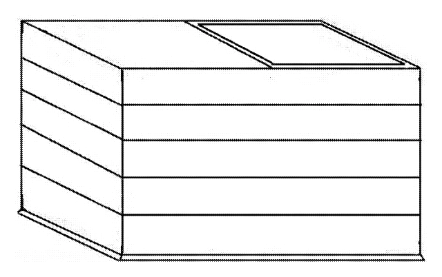
Hard-Shell Rooftop Tent That Doubles as a Cargo Box
Roof box whose hard frames lift on gas struts into a tent with door and skylight, and fold back for luggage.
Patent CN206327275U
Car Accessories
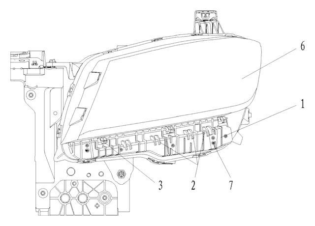
Headlamp-to-Bumper Adapter Bracket That Sets Gap and Flush in Three Directions
Molded bracket under the headlamp: support blocks and snap teeth locate the bumper flange for an even gap.
Patent CN216580316U
Car Accessories
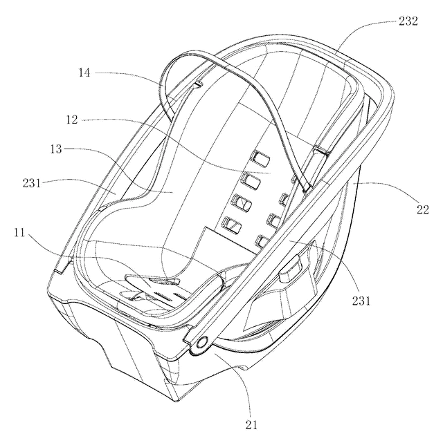
Infant Car Seat with a Load-Bearing Base That Wraps the Carrier
Infant car seat whose base has a backrest and swing-up side rails, so the carrier can be lighter.
Patent CN206383856U
Car Accessories
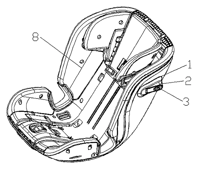
Retractable Side Impact Protection Block for Child Car Seats
Retractable side-impact block for child seats: springs out to provide side-impact buffering, folds flat.
Patent CN207028930U
Car Accessories
Rain-Deflecting Side Mirror with a Pivoting Air-Guide Plate
Side mirror with a top air duct and folding guide plate that directs airflow across the glass.
Patent CN207345672U
Browse by category
- Apparel & Accessories (28)
- Baby & Kids (20)
- Bags & Luggage (12)
- Bath & Personal Care (21)
- Car Accessories (16)
- Furniture, Bedding & Storage (15)
- Garden & Outdoor (21)
- Health & Wellness (10)
- Home, Kitchen & Cleaning (32)
- Lighting (15)
- Packaging & Containers (8)
- Pet Products (7)
- Phone & Camera Accessories (5)
- Retail Display (16)
- School, Office & Art (22)
- Sports & Recreation (30)
- Tools & Workshop (36)
- Toys & Games (15)
This page is based on the public patent document CN118405064B, assigned to Changzhou Yuhang Automotive Trim Co. IP2M is an independent manufacturing service and is not affiliated with, endorsed by or licensed by the patent owner. Images marked as concept renderings are illustrations, not photos of an existing product. Patent status information is provided for reference only and is not legal advice; confirm freedom to operate for your market before production. Full disclaimer.