
Patent CN118517621B
Updated November 6, 2026Anti-Glare Display Cart with Height Adjustment and Edge Clamping
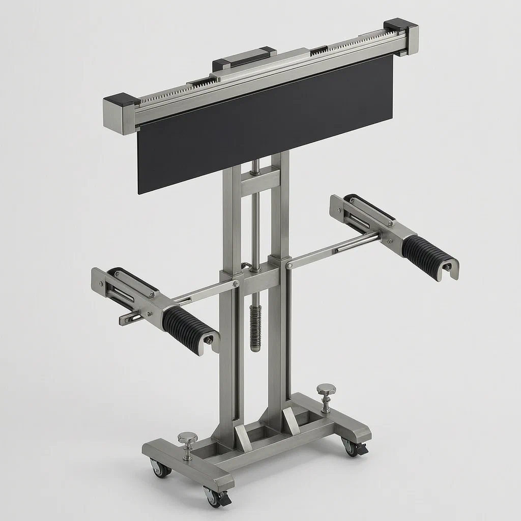
Standard AV carts often wobble, lack precise height control, or leave expensive projection panels exposed to glare and accidental knocks. This design solves those issues with a mechanical approach. The base secures itself to the floor using threaded screws that drop pressure pads and anchor pins. The screen mount clamps the panel symmetrically using a single gear driving two rack-and-pinion slides. When the user rotates the screen to their preferred viewing angle, a hemispherical detent snaps into place, and a secondary locking pin engages a rubber sleeve to prevent any drift during use.
- China invention patent - in force
- No filings outside China
- Education & AV equipment
- Manual lift, floor braking, edge clamping
Splat! What let you down?
🛑
Screw-Lock Braking
Threaded screws extend pressure blocks and anchor pins into the floor for stability.
⚙️
Bevel-Gear Lifting
A manual turntable drives bevel gears and a lead screw to adjust screen height smoothly.
🤏
Symmetric Clamping
One central gear moves two rack-driven slides to grip the screen evenly on both sides.
🔒
Rotation Locking
Spring-loaded push rods engage a toothed sleeve to lock the screen's tilt angle securely.
Bring this product to market
- ✓ Patent review Patent family and legal status reviewed in the relevant jurisdictions.
- 2 Product brief · now How it works, uses and options written up
- 3 Prototype First samples for buyers to review
- 4 Pilot run Small first batch for launch customers
- 5 Volume production Repeat orders at scale
Buyer interest
– of 100 buyers needed to start prototyping
One click, no sign-up. Each vote is one real visitor, and products with the most interest go to prototyping first.
Build team: no members yet. Need a partner, co-funding or skills to build this? Join and we introduce the team once it forms.
Patent Rights & Team Participation
Before joining a development team, participants should ensure they have the necessary rights or authorization to participate in the project.
Participation is generally appropriate where:
- You own the relevant patent rights or have obtained permission or a license from the rights holder.
- The relevant patent rights have expired or have been legally invalidated in the jurisdictions where the planned activities will take place.
- The planned development, manufacturing, and commercialization activities have been independently assessed and do not infringe applicable patent rights in the relevant jurisdictions.
Important: Being located outside a country where a patent is protected does not automatically exempt you from patent infringement risks. Patent rights may apply based on where development, manufacturing, use, sale, or import activities take place.
IP2M does not grant any patent license or authorization through team participation. Joining a project does not provide permission to use, manufacture, or commercialize patented technology.
The problem
Interactive displays used in classrooms and meeting rooms are often mounted on basic stands that offer poor stability. If the stand is not locked to the floor, bumping the table can cause the expensive screen to tip over. Furthermore, many carts lack precise height adjustment, forcing users to look up or down uncomfortably. Finally, securing the screen itself is problematic; simple brackets do not accommodate different bezel sizes, and loose mounts allow the screen to rotate out of position during active teaching sessions where the cart is frequently moved or adjusted.
The solution
The cart addresses these issues through three main mechanical systems:
- Base Stability: The “I”-shaped base has two caster wheels for mobility. For stationary use, threaded screws at each end drive trapezoidal pressure blocks downward. These blocks have anti-slip pads and internal roller shafts with hexagonal control slots. Turning the rollers moves plug pins through L-shaped slots to lock the blocks against the floor.
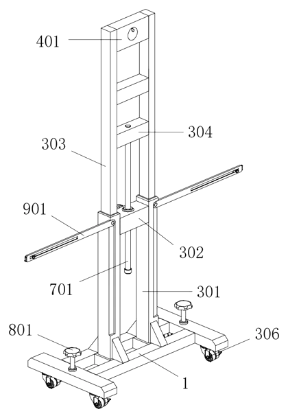
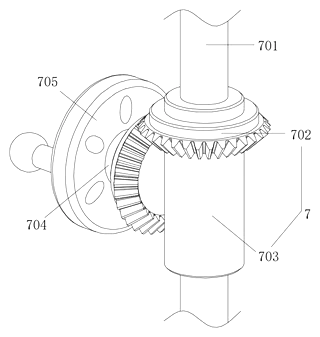
- Height Adjustment: Two parallel vertical columns rise from the base. A horizontal plate connects them, housing a bevel-gear system. A user turns an external knob (turntable), which rotates a connecting shaft and bevel gears to drive a vertical lead screw. This lifts or lowers the upper support structure holding the screen.
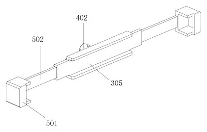
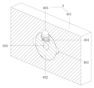
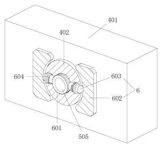
- Screen Mounting: The screen sits in a concave fixing seat. Two slide plates with racks mesh with a central gear, moving inward to clamp the screen edges simultaneously. A limiting mechanism uses spring-loaded push rods to engage a toothed rubber sleeve on the pivot axis, locking the screen’s rotation angle after it is set via a hemispherical detent.
Who it is for
- Educational Equipment Brands: Companies supplying classroom technology who need robust, adjustable stands for anti-glare projection screens and interactive whiteboards.
- AV Integrators: Installers setting up meeting rooms where screen height must match specific table configurations and audience seating.
- Corporate Furniture Manufacturers: Makers of conference tables who want to offer compatible mobile display solutions that don’t rely on wall mounting.
- Exhibition Booth Designers: Professionals needing secure, freestanding displays that can be locked down quickly at trade shows without damaging floors excessively.
How it works
The main parts
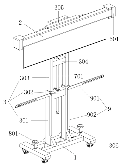
| No. | Part | What it does |
|---|---|---|
| 1 | Base | “I”-shaped frame with casters and braking screws. |
| 2 | Screen Body | The anti-glare interactive all-in-one unit. |
| 301, 303 | Columns & Support Rods | Vertical tracks for the lifting mechanism. |
| 305 | Fixing Seat | Concave holder that clamps the screen. |
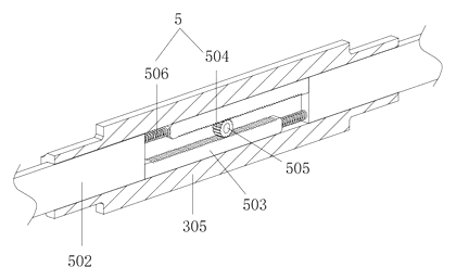
| 502, 503 | Slides & Racks | Move inward/outward to grip the screen edges. |
| 504 | Gear Plate | Drives both racks simultaneously for even clamping. |
| 601, 603 | Rubber Sleeve & Push Rods | Locks the rotation angle of the screen mount. |
| 701, 702 | Lead Screw & Bevel Gears | Translates rotary motion from the knob into vertical lift. |
| 801, 802 | Brake Screws & Pressure Blocks | Anchor the base to the floor. |
Operating steps
- Positioning: Roll the cart to the desired location. Turn the brake screws at the base corners. The pressure blocks descend, and the roller shafts are turned to extend anchor pins into the floor, stopping movement.
- Clamping: Place the screen into the concave seat. Turn the handle on the fixing seat. The central gear rotates, driving the two racks and slide plates inward. The clamping blocks grip the left and right edges of the screen body evenly.
- Adjusting Height: Rotate the external turntable on the support column. The bevel gears drive the vertical lead screw, raising or lowering the entire screen assembly along the columns.
- Setting Angle: Tilt the screen to the preferred viewing angle. As the fixed shaft rotates, the hemispherical protrusion snaps into one of the annular grooves in the top plate. Simultaneously, the push rods are forced outward by the cam action, pressing against the toothed rubber sleeve to prevent the screen from rotating back or drifting.
Applications
Classroom Teaching
Teachers move the cart between desks. The screw-lock base prevents tipping when students accidentally bump the stand. The height adjustment allows the screen to be lowered for younger students or raised for visibility in large lecture halls.
Conference Rooms
During presentations, the screen needs to be at eye level for seated participants. The smooth bevel-gear lift allows quick adjustments without tools. The rotation lock ensures the screen doesn’t shift when adjusted during collaborative work.
Trade Shows and Exhibitions
Booth displays need to be secure but movable. The anchor pins provide stability on hard floors without permanent installation. The clamping mechanism holds various sizes of anti-glare panels securely, protecting expensive assets from theft or accidental knocks.
Medical Consultation Rooms
Doctors use wall-mounted displays for patient data during consultations. The cart can be positioned next to the examination bed. The stable base keeps the screen steady while the doctor points at or writes notes beside it, and the height adjusts to fit the doctor’s standing posture.
Where it is less suitable
- Very Heavy Industrial Monitors: The clamping mechanism is designed for standard-sized educational/AV panels; extremely heavy industrial screens may require reinforced brackets.
- Rough Outdoor Surfaces: The anchor pins and pressure blocks work best on smooth indoor floors (tile, wood, concrete); they may not secure effectively on gravel or carpeted surfaces.
- Ceiling-Mounted Setups: This is a floor-standing solution; it does not replace overhead projector mounts or wall brackets.
Patent & Production
At a glance
| Patent number | CN118517621B (application CN202410993393) |
| Type | China invention patent (发明专利) - protects product method and structure |
| Original title | Anti-light curtain integrated machine trolley (一种抗光幕一体机推车) |
| Patent owner | Zhangjiagang Wanshida Electronic Teaching Technology Co ltd |
| Inventors | Chen Yongxiang |
| Filing date | 2024-07-24 |
| Grant date | 2024-11-19 |
| Status (China) | In force - valid until at most 2044-07-24 if annual fees are paid |
| Patent family | Public record shows Chinese filings only - no US, European, Japanese, PCT or other filings listed |
| Cited by | 0 later documents |
| Source | Google Patents (search for CN118517621B) |
What the claims cover, in plain language
Claim 1 defines the core cart structure: a base (1), support mechanism (3), screen body (2), and several functional mechanisms installed on the support. Specifically, it details the braking mechanism (8) which uses threaded screws (801) to drive pressure blocks (802) downwards. These blocks contain roller shafts (805) with hexagonal control slots and plug pins (807) that slide into L-shaped rotation grooves (804) to lock the pressure block. It also describes the support mechanism (3) comprising parallel columns (301) and a concave fixing seat (305).
Claim 2 specifies the base is “I”-shaped with universal wheels (306) and the pressure blocks are trapezoidal with anti-slip pads (803).
Claim 3 introduces the reinforcement mechanism (9), consisting of rotating rods (901) stored in grooves (902) on the columns.
Claim 4 details the reinforcement rods’ sliding blocks (904) and bolts (905) for adjusting stay ropes.
Claim 5 describes the rotating mechanism (4), using a fixed shaft (402) connected to the fixing seat.
Claim 6 adds the locking feature: three annular grooves (403) in the top plate and a spring-loaded hemispherical protrusion (405) on the shaft for indexing angles.
Claims 7-9 define the clamping mechanism (5) and limiting mechanism (6). Slides (502) with racks (503) are driven by a central gear (504) to grip the screen. A toothed rubber sleeve (601) and spring-loaded push rods (603) lock the rotation axis when the screen is angled.
Claim 10 specifies the lifting mechanism (7): a lead screw (701) driven by bevel gears (702) and a turntable (705) to raise/lower the support rods (303) along the columns.
This is a simplified reading for orientation only. The legal scope is defined by the exact claim wording in the official Chinese document.
What this means for US production
This patent was filed in China and is currently in force. Making or selling this specific design in China requires the owner’s permission. However, the public record shows no US counterpart. Therefore, this Chinese patent does not restrict manufacturing or sales in the United States based on its own existence.
Two points to settle early:
- Other patents may exist. Display carts and AV furniture are a competitive field with numerous existing patents covering height-adjustable stands, locking bases, and screen mounts. A freedom-to-operate (FTO) review is essential before tooling to ensure no US patents cover similar mechanical braking or clamping methods.
- Mechanical Complexity. The combination of screw-brakes, bevel-gear lifts, and synchronized clamps involves multiple precision-machined parts. Tooling costs will be higher than for simple tube-and-joint carts.
Customization and manufacturing
What can be customized
| Area | Options |
|---|---|
| Screen Size | Clamp slide length and gear ratio set for your target panel width |
| Lift Range | Column height and lead screw pitch for different room ceilings |
| Finish | Powder coating colors for base/columns; black/white for plastic parts |
| Wheels | Locking casters vs. standard swivel; wheel diameter |
| Brake Type | Foot-lever brakes could replace screw-knobs for faster deployment |
| Mount Interface | VESA adapter plates inside the concave seat for non-integrated screens |
Things to plan for (US market)
- UL 60950 / IEC 62368 - Safety standards for AV equipment. While the cart is passive, if sold as a bundle with electronics, certification applies.
- ANSI/BIFMA X5.9 - Storage units, though less common for carts, stability tests may reference similar protocols.
- California Prop 65 - Plastics and coatings must be screened for restricted substances.
- Load Rating Labels - US buyers expect clear weight limits printed on the product.
How a project runs
- Inquiry - Target screen sizes, lift range, quantity.
- Design - CAD modeling of gear ratios, column profiles, and brake mechanisms.
- Prototype - CNC machined metal parts and 3D printed plastics for fit checks.
- Pilot Run - Cycle testing for lift and clamp mechanisms; load tests for stability.
- Production - Injection molding for gears/handles; CNC machining for columns/screws; assembly.
Quantities & timeline
The lifting mechanism requires precision bevel gears and lead screws, likely necessitating CNC machining or high-grade powder metallurgy. The clamping system uses injection-molded racks and gears. The base requires welded steel fabrication and threaded inserts. Development time focuses on tuning the gear ratios for smooth lifting and ensuring the locking pins engage reliably. Send us your target screen sizes, lift range, finish preferences, quantity and target price and we will reply with options.
Production notes
Tooling and process
Aluminum columns and steel bases typically require CNC machining and press-fit assembly. Plastic components like the gear plates, handles, and slide blocks likely use PC or ABS injection molding. No magnets or electronics are part of this design; the mechanisms are purely mechanical.
Cost drivers
Mold count is typically significant due to the complex geometry of the clamping slides and locking sleeves. CNC time for the bevel gears and lead screws drives unit cost. Finish quality on visible aluminum parts affects pricing. Packaging must protect the heavy base and the screen mounting hardware.
Prototyping path
Start with a 3D-printed fit sample, likely the fastest way to verify the rack-and-pinion clamping synchronization. Use CNC housings for the lifting mechanism to test torque requirements. Focus on mechanical stress tests for the screw-brakes and durability cycles for the lift. Tooling follows once kinematics are validated.
What we would change before tooling
The hexagonal control slot for the brake pins might be difficult to mold precisely; consider simplifying to a square or D-shape if function allows. The spring-loaded push rod mechanism relies on tight tolerances; adding a bushing could reduce wear. Wall thickness and joint design on the plastic slides should be optimized to prevent cracking under clamp tension.
Common failure points
Shaft and bearing alignment in the lifting mechanism can cause binding if columns warp. Spring fatigue in the locking push rods may reduce retention force over time. Thread engagement on the base brake screws can strip if overtightened. Adhesive failure is unlikely as screws are primary fasteners, but plastic clips may snap if misaligned. Clamp gear wear may loosen grip over time.
Patent drawings
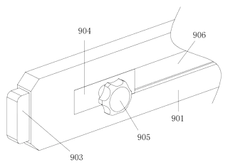
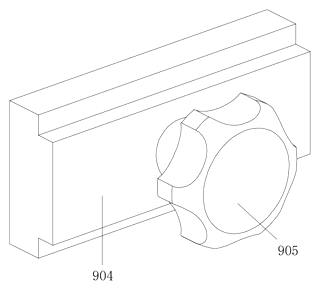
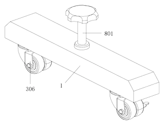
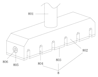
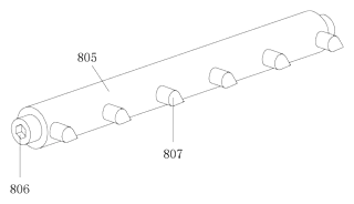
Drawings reproduced from the public patent document for reference.
Frequently asked questions
How does the base stay stable?
It uses a screw-driven braking system. At each corner of the “I”-shaped base, turning a threaded screw pushes a trapezoidal pressure block down onto the floor. Inside the block, a roller shaft turns pins through L-shaped slots to lock the block in place. This locks the cart firmly in place without needing wall anchors.
Can the screen height be adjusted easily?
Yes. There is a manual turntable on the side of the support column. Rotating it drives a set of bevel gears and a vertical lead screw. This raises or lowers the entire screen assembly smoothly along the two parallel columns. It allows for quick changes between sitting and standing positions.
Will the screen fall off if someone touches it?
No. The screen is held in a concave seat by a synchronized clamping mechanism. A central gear drives two slide plates inward, gripping the left and right edges of the screen body evenly. Additionally, a locking mechanism engages when the screen is tilted, preventing it from rotating out of position during use.
Does it work with any size anti-glare panel?
The clamping slides are adjustable within a range. However, the gear ratio and slide length determine the maximum and minimum screen widths. We can customize the internal spacing to fit specific panel sizes (for example, about 55 to 86 inches). Contact us with your screen dimensions for compatibility checks.
Is the setup complicated?
Assembly involves bolting the base to the columns and installing the gear mechanisms. The patent describes a modular structure. Once assembled, operation is purely mechanical: turn knobs for braking and lifting, and turn a handle for clamping. No electrical wiring is required for the cart itself.
Can this design be made and sold in the US?
The patent was filed in China and is currently in force there. However, the public record shows no US counterpart. This means the Chinese patent does not restrict manufacturing or sales in the United States. Note that other US patents may cover similar AV cart features, so a freedom-to-operate review is recommended before volume production.
Are you affiliated with the patent owner?
No. IP2M is an independent design and manufacturing service working from the public patent document.
Request a quote
Click Request a Quote below to see our email address - copy it, or open your email app with a ready-made message. Please mention patent CN118517621B in the subject.
Helpful details to include:
- Your company and channel (education supplier, AV integrator, furniture maker)
- Target screen sizes (width and depth of the panels)
- Required lift range (minimum and maximum height)
- Finish preferences (colors for metal and plastic parts)
- Estimated quantity and target price
- Timeline - when you would like samples and the first shipment
You can also reach us at (332) 203-9997.
Page editor: Daniel Chen, Product Research Editor · IP2M
Last updated November 6, 2026. If something on this page looks wrong, email [email protected] and we will check it against the patent.
Interested in building this?
Tell us your target market, quantity and timeline. We reply with options for prototyping, small-batch runs or volume production.
Send your inquiry to
Please put CN118517621B in the subject line and tell us your company, country, estimated quantity and timeline.
Prefer to talk? Call (332) 203-9997.
More product-ready patents
All Phone & Camera Accessories patents →
Phone & Camera Accessories
Phone Clip Mount with Fold-Out Stand Leg
Phone clamp adapter with a ball-joint top, a dovetail base for tripod clamps and a fold-out desk leg.
Patent CN207394276U
Stands & Mounts
Manual Quick-Release Connector for Camera Equipment
Quick-release camera mount using a rotating driver and spring-loaded locking grooves.
Patent CN215294199U
Phone & Camera Accessories
Extendable Support Leg and Monopod with Single-Knob Locking
Three-section monopod leg locked and released from one top knob via a transmission rod.
Patent CN113090903B
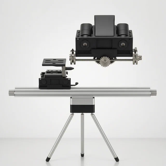
Phone & Camera Accessories
Remote-Controlled Outdoor Photography Tripod with Movable Lens Mount
Motorized tripod with a remote-driven camera seat and a sliding multi-lens mount.
Patent CN118328254B
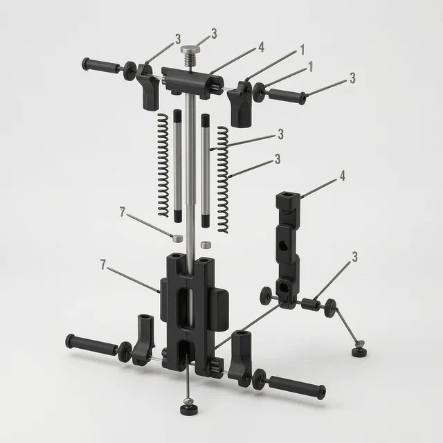
Phone & Camera Accessories
Foldable Multifunctional Mobile Phone Clip with Rotating Support Feet
Foldable phone clip with rotating tripod-compatible feet and 1/4-inch screw mounts.
Patent CN207112268U
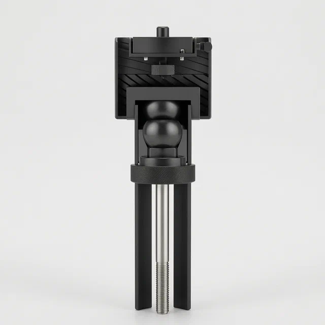
Phone & Camera Accessories
One-Touch Locking Ball Head Mount for Cameras and Equipment
Single-knob ball head mount that locks the ball and secures the device in one rotation.
Patent CN220930728U
Browse by category
- Apparel & Accessories (43)
- Baby & Kids (28)
- Bags & Luggage (16)
- Bath & Personal Care (29)
- Car Accessories (23)
- Furniture, Bedding & Storage (22)
- Garden & Outdoor (29)
- Health & Wellness (13)
- Home, Kitchen & Cleaning (46)
- Lighting (22)
- Packaging & Containers (11)
- Pet Products (10)
- Phone & Camera Accessories (9)
- Retail Display (23)
- School, Office & Art (33)
- Sports & Recreation (41)
- Tools & Workshop (50)
- Toys & Games (21)
This page is based on the public patent document CN118517621B, assigned to Zhangjiagang Wanshida Electronic Teaching Technology Co ltd. IP2M is an independent manufacturing service and is not affiliated with, endorsed by or licensed by the patent owner. Images marked as concept renderings are illustrations, not photos of an existing product. Patent status information is provided for reference only and is not legal advice; confirm freedom to operate for your market before production. Full disclaimer.