
Patent CN118560401B
Updated October 29, 2026Lifting Phone Tray Mechanism for Vehicle Cockpits
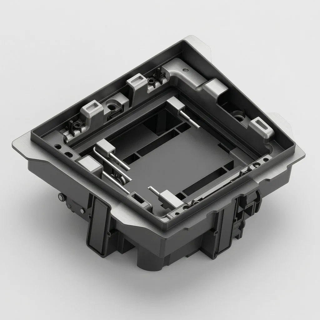
Fixed phone slots in vehicles often leave devices exposed or hard to reach. This lifting mechanism solves that by raising the tray when needed and hiding it completely inside the base when not in use. A driving part, such as a motor, turns a drive shaft connected to end plates. These plates feature arc-shaped grooves whose distance from the rotation axis gradually increases. Support rods inserted into these grooves push the tray upward as the plates turn. Multiple brackets can be linked together for synchronized movement, keeping the tray level during operation.
- China invention patent - in force
- No filings outside China
- Vehicle cockpit hardware
- Motor-driven cam and rod lift
Splat! What let you down?
⬆️
Vertical lifting
The tray moves up and down along a first direction driven by a rotating bracket.
🔄
Arc-groove conversion
Grooves with increasing radius on the end plates convert rotation into linear lift.
📦
Flush storage
When lowered, the tray is fully accommodated inside the base.
🔗
Synchronized linkage
Multiple driving brackets can be linked to rotate together for stable lifting.
Bring this product to market
- ✓ Patent vetted China-only family and legal status checked
- 2 Product brief · now How it works, uses and options written up
- 3 Prototype First samples for buyers to review
- 4 Pilot run Small first batch for launch customers
- 5 Volume production Repeat orders at scale
Buyer interest
– of 100 buyers needed to start prototyping
One click, no sign-up. Each vote is one real visitor, and products with the most interest go to prototyping first.
Build team: no members yet. Need a partner, co-funding or skills to build this? Join and we introduce the team once it forms.
The problem
Standard phone compartments in vehicle dashboards present two main issues. First, when a slot is open and empty, it collects dust, coins, or debris, and leaves a visible hole in the interior trim. Second, fixed slots offer limited room for phones with thick protective cases, and during sudden stops or sharp turns, devices can slide out or rattle against the hard plastic walls. Drivers also struggle to retrieve phones from deep, fixed pockets without taking their eyes off the road for too long.
The solution
This mechanism addresses those issues through a motorized lifting tray.
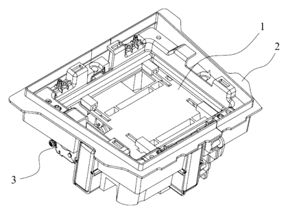
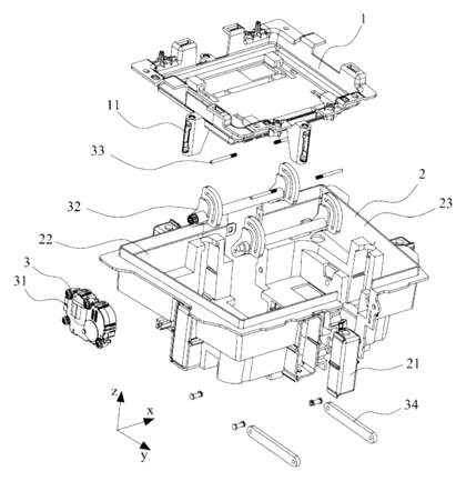
- A tray (1) sits on a base (2) and holds the electronic device.
- A driving assembly (3) mounted on the base connects to the tray and drives it to lift relative to the base along a first direction (z).
- When the tray descends, it is completely accommodated within the base, closing off the opening.
- The driving assembly includes a driving part (31), a driving bracket (32), and a supporting piece (33).
- The driving bracket rotates around a rotation axis extending along a second direction (x).
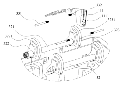
- A first end plate (322) on the bracket features a first arc-shaped groove (3221). The distance between this groove and the rotation axis gradually increases from one end to the other.
- A first support rod (331) connects the tray to the groove. As the bracket turns, the changing groove radius pushes the rod and the tray vertically.
Who it is for
- Automotive OEMs and Tier 1 suppliers integrating concealed, motorized device storage into new center console or dashboard designs.
- Aftermarket car accessory brands developing premium add-on modules for existing vehicle models lacking built-in phone holders.
- Commercial fleet outfitters equipping delivery vans or ride-share vehicles with secure, hidden device mounts to reduce cabin clutter and theft risk.
- RV and specialty vehicle builders needing adaptable electronic equipment carriers that retract flush with interior surfaces to save living space.
How it works
The main parts
| No. | Part | What it does |
|---|---|---|
| 1 | Tray | Holds the electronic device (e.g., mobile phone). |
| 2 | Base | Houses the mechanism; receives the tray when lowered. |
| 3 | Driving assembly | Provides the lifting and lowering motion. |
| 31 | Driving part | A motor or rotary cylinder that powers the drive shaft. |
| 32 | Driving bracket | Rotates around the axis; includes the drive shaft and end plates. |
| 321 | Drive shaft | Connects to the driving part; its axis coincides with the rotation axis. |
| 322 | First end plate | Connected to the shaft; contains the first arc-shaped groove. |
| 3221 | First arc-shaped groove | Guides the support rod; radius increases along its length. |
| 323 | Second end plate | Parallel to the first; contains the second arc-shaped groove. |
| 33 | Supporting piece | Links the bracket to the tray via support rods. |
| 331 | First support rod | One end pivots on the tray, the other inserts into the first groove. |
| 332 | Second support rod | Coaxial with the first; inserts into the second groove. |
Operating steps
- Activation - The driving part (31), such as a motor, receives a signal and turns the drive shaft (321).
- Rotation - The shaft rotates the driving bracket (32) around the rotation axis (second direction x).
- Conversion - Because the arc-shaped grooves (3221, 3231) have a gradually increasing distance from the axis, the rotating end plates push the support rods (331, 332) outward.
- Lifting - The rods transfer this motion to the tray (1), moving it along the first direction (z) away from the base (2).
- Lowering - Reversing the motor pulls the rods back along the grooves, allowing the tray to descend until it is fully accommodated inside the base.
Applications
Daily commuting
Drivers place their phones on the tray before starting the car. The mechanism lifts the device to a readable height for navigation, eliminating the need to look down into a deep console pocket.
Ride-share and taxi services
Operators lower the tray into the base when no passenger is present. This hides the driver’s personal device or payment terminal, reducing visual clutter and protecting equipment from tampering.
Commercial delivery fleets
Delivery drivers frequently enter and exit vehicles. A flush-mounted tray prevents loose items from falling into the phone slot during rough driving or sudden stops, keeping the cabin organized.
Luxury vehicle interiors
Designers use the mechanism to maintain seamless dashboard surfaces. When retracted, the tray disappears entirely into the base, preserving the aesthetic lines of the cockpit trim.
Where it is less suitable
- Rugged off-road vehicles - environments with heavy mud, water, or extreme vibration may require sealed, fixed mounts rather than moving mechanical parts.
- Low-cost economy cars - the motor, shafts and arc-shaped guide grooves add cost compared to simple friction-fit rubber slots.
- Tablet-sized devices - the patent describes carrying a mobile phone; larger tablets would require dimensions to be confirmed in design.
Frequently asked questions
How does the tray move up and down?
A motor turns a drive shaft connected to end plates. These plates have arc-shaped grooves where the distance from the center axis gradually increases. Support rods sit inside these grooves and connect to the tray. As the plates rotate, the widening groove radius pushes the rods outward, lifting the tray vertically.
Does it use a specific type of motor?
The patent states the driving part can be a motor with an output shaft connected to the drive shaft, or other structures capable of rotary driving, such as a rotary cylinder. The exact motor specifications are set in design based on the tray weight and desired speed.
Will the tray stay level while lifting?
Yes. The patent describes using a second end plate parallel to the first, with a second arc-shaped groove and a second support rod coaxial with the first. For wider trays, multiple driving brackets can be spaced apart and linked together by a linkage piece so they rotate synchronously.
Can it fit any smartphone?
The patent specifies the tray carries electronic equipment such as a mobile phone. Exact internal dimensions to accommodate different phone sizes and cases are to be confirmed in design.
Is this only for factory-installed dashboards?
No. While the patent mentions a vehicle cockpit, the mechanism could be engineered as an aftermarket module that fits into existing console spaces, provided the base dimensions are adapted.
What happens if the power fails?
The patent focuses on the mechanical lifting structure. Fail-safe behavior, such as manual override or spring return, is not described and would need to be planned during the engineering phase.
Can this design be made and sold in the US?
This patent was filed only in China and is in force in China until at most 2044-07-29 (if annual fees are paid). It does not restrict making or selling the design in the US. However, motorized vehicle mounts may be covered by other US patents held by automotive suppliers, so we recommend a freedom-to-operate check before volume production.
Are you affiliated with the patent owner?
No. IP2M is an independent design and manufacturing service working from the public patent document.
Request a quote
Click Request a Quote below to see our email address - copy it, or open your email app with a ready-made message. Please mention patent CN118560401B in the subject.
Helpful details to include:
- Your company and channel (automotive OEM, Tier 1 supplier, aftermarket brand, fleet outfitter)
- Target vehicle platform or console dimensions
- Tray size requirements for the intended devices
- Preferred driving part (DC motor, stepper, etc.)
- Estimated quantity and target price
- Timeline - when you would like prototypes and the first shipment
You can also reach us at (332) 203-9997.
Explore this product
Interested in building this?
Tell us your target market, quantity and timeline. We reply with options for prototyping, small-batch runs or volume production.
Send your inquiry to
Please put CN118560401B in the subject line and tell us your company, country, estimated quantity and timeline.
Prefer to talk? Call (332) 203-9997.
More product-ready patents
All Car Accessories patents →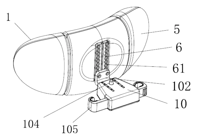
Car Accessories
Car Headrest Pillow with Ratchet Side Wings and Push-Button Reach
Post-mounted car headrest pillow with ratchet side wings and a push-button forward adjustment.
Patent CN212195197U
Car Accessories
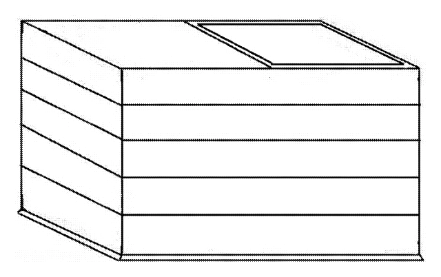
Hard-Shell Rooftop Tent That Doubles as a Cargo Box
Roof box whose hard frames lift on gas struts into a tent with door and skylight, and fold back for luggage.
Patent CN206327275U
Car Accessories
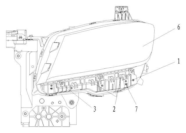
Headlamp-to-Bumper Adapter Bracket That Sets Gap and Flush in Three Directions
Molded bracket under the headlamp: support blocks and snap teeth locate the bumper flange for an even gap.
Patent CN216580316U
Car Accessories
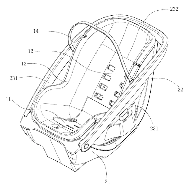
Infant Car Seat with a Load-Bearing Base That Wraps the Carrier
Infant car seat whose base has a backrest and swing-up side rails, so the carrier can be lighter.
Patent CN206383856U
Car Accessories
Retractable Side Impact Protection Block for Child Car Seats
Retractable side-impact block for child seats: springs out to provide side-impact buffering, folds flat.
Patent CN207028930U
Car Accessories
Rain-Deflecting Side Mirror with a Pivoting Air-Guide Plate
Side mirror with a top air duct and folding guide plate that directs airflow across the glass.
Patent CN207345672U
Browse by category
- Apparel & Accessories (22)
- Baby & Kids (16)
- Bags & Luggage (9)
- Bath & Personal Care (16)
- Car Accessories (10)
- Furniture, Bedding & Storage (12)
- Garden & Outdoor (18)
- Health & Wellness (8)
- Home, Kitchen & Cleaning (24)
- Lighting (12)
- Packaging & Containers (6)
- Pet Products (6)
- Phone & Camera Accessories (4)
- Retail Display (13)
- School, Office & Art (19)
- Sports & Recreation (25)
- Tools & Workshop (27)
- Toys & Games (12)
This page is based on the public patent document CN118560401B, assigned to BYD Co Ltd. IP2M is an independent manufacturing service and is not affiliated with, endorsed by or licensed by the patent owner. Images marked as concept renderings are illustrations, not photos of an existing product. Patent status information is provided for reference only and is not legal advice; confirm freedom to operate for your market before production. Full disclaimer.