
Patent CN118564871B
Updated October 29, 2026Street Lamp Angle Adjusting Mechanism with Rotatable Reflectors
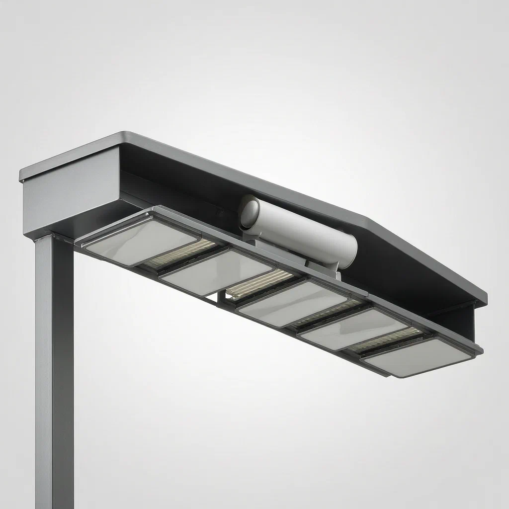
Fixed-height street lamps often cast light beyond the road surface, sending direct glare into nearby buildings because the tilt alone cannot shape the beam's edge. This mechanism solves that by combining housing rotation with adjustable reflective plates. A servo motor and gear set inside the mounting box turn the entire housing. Inside each light box assembly, a pushing assembly slides a linkage rod that runs through all the boxes. That rod moves guide pins in strip-shaped holes on lifting frames, which pivot rotating connecting rods attached to the backs of the reflective plates. As the plates tilt, the reflected light narrows or widens to match the road below.
- China invention patent - in force
- No filings outside China
- Outdoor lighting hardware
- Servo motor, gear set, linkage rod, reflective plates
Splat! What let you down?
🔄
Housing rotation
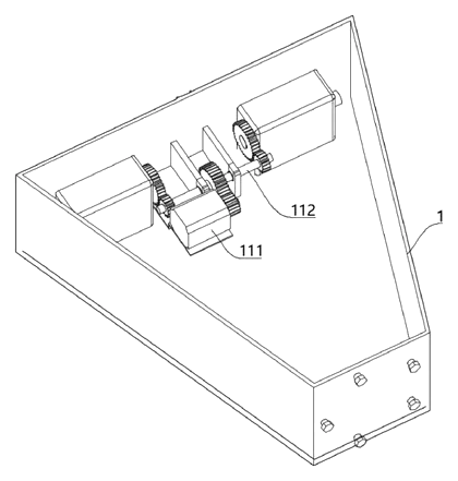
A servo motor and gear set inside the mounting box turn the housing to adjust the overall aim.
🪞
Rotatable reflective plates
Reflective plates on both sides of the light board pivot to shape the beam edge.
🔗
Linked adjustment
One linkage rod slides through multiple light box assemblies to adjust all reflectors together.
🛑
Glare reduction
Controlling the reflector angle directs light onto narrow roads, keeping it off nearby buildings.
Bring this product to market
- ✓ Patent vetted China-only family and legal status checked
- 2 Product brief · now How it works, uses and options written up
- 3 Prototype First samples for buyers to review
- 4 Pilot run Small first batch for launch customers
- 5 Volume production Repeat orders at scale
Buyer interest
– of 100 buyers needed to start prototyping
One click, no sign-up. Each vote is one real visitor, and products with the most interest go to prototyping first.
Build team: no members yet. Need a partner, co-funding or skills to build this? Join and we introduce the team once it forms.
The problem
When a street lamp is mounted at a fixed height, tilting the fixture changes the general direction of the beam but does not control where the edges of the light fall. On narrow streets, the outer portions of the beam often spill past the pavement. Direct light strikes roadside buildings, causing glare for residents and wasting energy on areas that do not need illumination. Conventional tilt brackets cannot reshape the beam width once the lamp is installed.
The solution
This mechanism uses two coordinated movements to aim the light precisely. First, a driving assembly inside a mounting box rotates the entire housing relative to the pole. Second, a pushing assembly inside the housing slides a linkage rod that passes through all the light box assemblies. That rod acts on lifting frames, which pivot the reflective plates on both sides of each light board. By changing the angle of the reflective plates, the system narrows or widens the reflected beam to match the exact width of the road below, keeping the light off adjacent structures.
Who it is for
- Municipal lighting contractors who install fixtures on narrow urban streets and need to prevent light spill onto residential facades without adding external shields.
- Commercial LED luminaire brands expanding their outdoor catalog with an adjustable-beam fixture that controls reflector angles mechanically from a single point.
- Smart city integrators requiring a motorized housing combined with mechanical beam shaping for automated road-lighting adjustments based on traffic or time of day.
- Wholesalers of outdoor lighting hardware supplying regional distributors who serve towns with varied road widths and strict glare ordinances.
How it works
The main parts
| No. | Part | What it does |
|---|---|---|
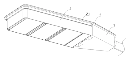
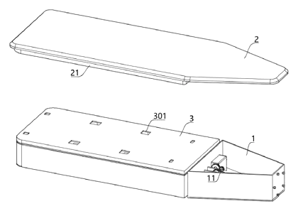
| 1 | Mounting box | Attaches to the street lamp pole; houses the driving assembly. |
| 2 | Cover plate | Covers the mounting box and housing connection. |
| 3 | Housing | Rotates on the mounting box; holds the light box assemblies. |
| 4 | Light box assembly | Contains the light board, reflective plates, and linkage parts. |
| 5 | Linkage rod | Slides horizontally through the light boxes to move the guide rods. |
| 6 | Pushing assembly | Pushes the linkage rod using a sliding rod, abutment plate, and elastic member. |
| 7 | Lamp post | Supports the mounting box (shown in reference). |
| 11 | Driving assembly | Servo motor and gear set that rotate the housing. |
| 12 | Rotating connection block | Transfers rotation from the gear set to the housing. |
| 41 | Box body | Outer shell of each light box assembly. |
| 42 | Light board | Fixed below the fixing plate; holds the light source. |
| 43 | Reflective plate | Pivots on both sides of the light board to direct light. |
| 44 | Fixing plate | Secures the light board inside the box body. |
| 45 | Lifting frame | Slides up and down above the fixing plate; has a strip-shaped through hole. |
| 46 | Guide rod | Fixed on the linkage rod; passes through the lifting frame’s hole. |
| 47 | Rotating connecting rod | Links the lifting frame ends to the back of the reflective plates. |
| 61 | Sliding rod | Part of the pushing assembly; passes through the housing. |
| 62 | Abutment plate | Fixed on the sliding rod; presses against the mounting box wall. |
| 63 | Elastic member | Biases the abutment plate toward the mounting box. |
| 111 | Gear set | Converts motor torque to rotate the connection block. |
| 112 | Servo motor | Powers the driving assembly. |
| 4501 | Strip-shaped through hole | Allows the guide rod to convert horizontal motion to vertical motion. |
Operating steps
- Rotate the housing - The servo motor (112) turns the gear set (111), which rotates the connection block (12) to tilt the housing (3) to the desired overall angle.
- Engage the pushing assembly - As the housing rotates, the abutment plate (62) rides along the outer wall of the mounting box (1). The elastic member (63) keeps the sliding rod (61) pressed against the box, translating the housing’s rotation into linear push on the linkage rod (5).
- Slide the linkage rod - The linkage rod (5) moves left or right through the multiple light box assemblies (4).
- Move the lifting frames - The guide rods (46) on the linkage rod travel through the strip-shaped through holes (4501) in the lifting frames (45), forcing the lifting frames to slide up or down.
- Pivot the reflectors - The vertical movement of the lifting frames (45) pushes or pulls the rotating connecting rods (47), which pivot the reflective plates (43) on both sides of the light board (42).
- Shape the beam - The new angle of the reflective plates (43) narrows or widens the reflected light path, matching the road width and preventing direct light from hitting buildings.
Applications
Narrow residential streets
Installers mount the fixture on standard poles where houses sit close to the curb. The mechanism narrows the beam so the light stays on the asphalt. Residents avoid direct glare shining through their windows at night.
Historic town centers
Older districts have uneven building lines and strict aesthetic rules that prohibit bulky external light shields. The internal reflector adjustment shapes the beam without altering the fixture’s exterior profile. Contractors meet local lighting ordinances while preserving the streetscape.
Highway ramps and merge lanes
Road widths change rapidly at highway exits. Maintenance crews adjust the housing rotation and reflector angles to follow the tapering lane. This keeps the illuminated area aligned with the traffic path as vehicles merge.
Industrial park perimeters
Security lighting along fences must cover the patrol road without casting bright spots into neighboring properties or blinding security cameras. The adjustable reflective plates confine the spill to the designated perimeter strip. Facility managers reduce complaints from adjacent lots.
Where it is less suitable
- Wide open parking lots - broad flood coverage requires different optics rather than narrow beam shaping.
- Decorative pedestrian bollards - low-level pathway lights do not use overhead housing rotation or complex linkage systems.
- Temporary construction lighting - portable work lights prioritize quick setup over precise mechanical reflector adjustment.
Frequently asked questions
How does the mechanism adjust the light beam?
A linkage rod slides horizontally through the light box assemblies. Guide rods on the linkage pass through strip-shaped holes in lifting frames, forcing the frames to move up and down. That vertical motion pivots rotating connecting rods attached to the backs of the reflective plates, changing their angle to narrow or widen the reflected light.
Does one motor control all the reflectors?
Yes. The linkage rod runs through multiple light box assemblies. When the pushing assembly slides the rod, it actuates the lifting frames and reflective plates in all connected boxes simultaneously, ensuring uniform beam shaping across the fixture.
How does the pushing assembly work when the housing rotates?
The pushing assembly has a sliding rod with an abutment plate that presses against the outer wall of the fixed mounting box. An elastic member biases the plate toward the box. As the servo motor rotates the housing, the interaction between the abutment plate and the stationary mounting box wall translates the rotational movement into linear sliding of the linkage rod.
What drives the overall tilt of the housing?
A servo motor inside the mounting box turns a gear set. The gear set rotates a connection block that extends into the mounting box from the housing. This allows the motor to apply higher torque to tilt the entire housing assembly.
Can the reflector angle be adjusted independently of the housing tilt?
The patent describes the pushing assembly engaging the mounting box wall during housing rotation to drive the linkage. The reflector adjustment is mechanically tied to the housing’s movement relative to the mounting box. Independent manual override is not described in the patent text and would be a feature to set in design.
What sizes of roads can this cover?
The patent does not specify maximum or minimum road widths. The achievable beam width depends on the length of the linkage travel, the geometry of the strip-shaped holes, and the size of the reflective plates, which are set in design and confirmed on prototypes.
Is the mechanism weather-sealed?
The patent mentions a cover plate that covers the mounting box and housing. Specific IP ratings or gasket details are not in the patent text; sealing methods are determined during product engineering.
Can this design be made and sold in the US?
The patent was filed only in China and is in force in China until at most 2044-07-12 (if annual fees are paid), so it does not restrict the design in the US. However, outdoor lighting mechanisms may be covered by other US patents - see Patent & Production - so we recommend a freedom-to-operate check before volume production.
Are you affiliated with the patent owner?
No. IP2M is an independent design and manufacturing service working from the public patent document.
Request a quote
Click Request a Quote below to see our email address - copy it, or open your email app with a ready-made message. Please mention patent CN118564871B in the subject.
Helpful details to include:
- Your company and channel (municipal contractor, luminaire brand, smart city integrator, wholesaler)
- Target road width and pole mounting height
- Number of light box assemblies per fixture
- Electrical specifications for the servo motor and light boards
- Estimated quantity and target price
- Timeline - when you would like prototypes and the first shipment
You can also reach us at (332) 203-9997.
Explore this product
Interested in building this?
Tell us your target market, quantity and timeline. We reply with options for prototyping, small-batch runs or volume production.
Send your inquiry to
Please put CN118564871B in the subject line and tell us your company, country, estimated quantity and timeline.
Prefer to talk? Call (332) 203-9997.
More product-ready patents
All Lighting patents →
Lighting
Wrist-Worn Flashlight with Click-Lock Angle Adjustment
Rechargeable wrist flashlight whose lamp turns and locks at an angle with a push button.
Patent CN113915544B
Lighting
Self-Folding Desk Lamp That Turns into a Phone Stand
Desk lamp with a shape-memory stem that unfolds when warm and folds into a phone stand.
Patent CN213237087U
Lighting
Ring-Shaped Outdoor Lantern That Lifts Off a Power-Bank Charging Base
Ring lantern with a battery handle that docks in a cone base with its own battery, clamp and charging plug.
Patent CN212408329U
Lighting
LED Flameless Candle with an Outside Flame Shade and Wax Dish Top
Battery LED candle: flame shade stands above a dished wax top, angled LEDs light a printed wick.
Patent CN205424561U
Lighting
Telescoping Tripod Portable Work Light with Fold-In Light Panels
Telescoping tripod work light with dual light panels that fold flat into the base.
Patent CN207298471U
Lighting
Self-Cooling and Self-Cleaning LED Street Light with Rainwater Harvesting
LED street lamp that harvests rain to cool its heat sink and spray-wash the lens automatically.
Patent CN205480639U
Browse by category
- Apparel & Accessories (22)
- Baby & Kids (16)
- Bags & Luggage (9)
- Bath & Personal Care (16)
- Car Accessories (10)
- Furniture, Bedding & Storage (12)
- Garden & Outdoor (18)
- Health & Wellness (8)
- Home, Kitchen & Cleaning (24)
- Lighting (12)
- Packaging & Containers (6)
- Pet Products (6)
- Phone & Camera Accessories (4)
- Retail Display (13)
- School, Office & Art (19)
- Sports & Recreation (25)
- Tools & Workshop (27)
- Toys & Games (12)
This page is based on the public patent document CN118564871B, assigned to Yangzhou Danding Road Lighting Co ltd. IP2M is an independent manufacturing service and is not affiliated with, endorsed by or licensed by the patent owner. Images marked as concept renderings are illustrations, not photos of an existing product. Patent status information is provided for reference only and is not legal advice; confirm freedom to operate for your market before production. Full disclaimer.