At a glance
| Patent number | CN118564871B (application CN202410933644) |
| Type | China invention patent (发明专利) - protects product shape, structure and method |
| Original title | Street lamp angle adjusting mechanism (一种路灯角度调节机构) |
| Patent owner | Yangzhou Danding Road Lighting Co ltd |
| Inventors | Xie Jiafeng |
| Filing date | 2024-07-12 |
| Grant date | 2024-12-17 |
| Status (China) | In force in China until at most 2044-07-12 (if annual fees are paid) |
| Patent family | Chinese filings only - no US, European, Japanese, PCT or other filings listed |
| Cited by | 0 later documents |
| Source | Google Patents (search for CN118564871B) |
What the claims cover, in plain language
Claim 1 - A street lamp angle adjustment mechanism comprising a mounting box installed on a lamp pole, with a housing rotatably mounted on the side away from the pole. A driving assembly inside the mounting box rotates the housing. Multiple light box assemblies are fixed inside the housing, each containing a light board with reflective plates rotatably mounted on both sides. A linkage rod slidably mounted above the light board drives the two reflective plates to rotate. A pushing assembly fixed inside the housing pushes the linkage rod to slide, adjusting the rotation angle of the reflective plates. Each light box assembly includes a box body with a fixing plate; the light board is fixed below it. A lifting frame slides up and down above the fixing plate, straddling it, with rotating connecting rods at its ends linked to the backs of the reflective plates. A guide rod on the linkage rod passes through a strip-shaped through hole in the lifting frame, converting horizontal sliding into vertical lifting frame movement. The pushing assembly includes a sliding rod passing through the housing, an abutment plate pressing against the mounting box wall, and an elastic member biasing the plate toward the box.
Claim 2 - Adds a rotating connection block fixed on the housing side facing the mounting box, extending into the box at a lower horizontal height than the pushing assembly. The driving assembly comprises a gear set and a servo motor, where the motor drives the connection block via the gear set.
Claim 3 - Adds a cover plate covering the mounting box and housing.
This is a simplified reading for orientation only. The legal scope is defined by the exact claim wording in the official Chinese document.
What this means for US production
This patent was filed only in China and is currently in force in China until at most 2044-07-12 (if annual fees are paid), meaning making or selling this exact mechanism in China needs the owner’s permission. It has no US or other foreign counterpart.
Two points to settle early:
- Other patents may exist. Outdoor LED luminaires and adjustable street lighting mechanisms are heavily patented globally, with various companies holding US and foreign patents on optical aiming, motorized tilt, and reflector arrays. Because no foreign patents cite this specific document, a freedom-to-operate (FTO) review of the linkage-driven reflector adjustment and the housing rotation method is needed before tooling.
- Motor and gear integration. The servo motor, gear set, and pushing assembly rely on specific spatial relationships inside the mounting box. Scaling the fixture for different lumen outputs or wind loads requires re-engineering these clearances and confirming the elastic member’s force on prototypes.
Customization and manufacturing
What can be customized
| Area | Options |
|---|---|
| Housing size | Dimensions to fit varying numbers of light box assemblies, to be confirmed in design |
| Reflector material | Aluminum, polycarbonate with reflective coating, or other optical substrates |
| Motor specification | Servo motor voltage and torque matched to the housing weight and wind load |
| Linkage mechanism | Rod diameter, guide pin profile, and strip-shaped hole geometry tuned for the required reflector angle range |
| Finish | Powder coating or anodizing for outdoor corrosion resistance |
| Optical output | Light board wattage and LED layout set in design |
Things to plan for (US market)
- UL 1598 / UL 8750 - Luminaires and LED equipment intended for installation in the US generally require safety certification by a Nationally Recognized Testing Laboratory (NRTL).
- FCC Part 15 - The servo motor and any associated electronic drivers must comply with FCC limits for unintentional radiators if they contain digital circuitry.
- DLC listing - Commercial buyers and utility rebate programs in the US frequently require DesignLights Consortium qualification for outdoor LED fixtures.
- IESNA RP-8 - Recommended practice for roadway lighting, which dictates photometric distribution types; the adjustable reflectors must be tested to verify they meet the target classifications.
How a project runs
- Inquiry - define the road width range, pole height, lumen requirements, and quantity.
- Design - engineer the mounting box, housing, linkage rod geometry, and gear set ratio; select the servo motor.
- Prototype - build samples to test the pushing assembly’s travel, the lifting frame’s smooth operation, and the reflector angle range.
- Pilot run - conduct photometric testing, cycle tests on the linkage, and environmental sealing checks.
- Production - die-cast or extrude housings, stamp the internal brackets, assemble the driving and pushing components, and wire the light boards.
Quantities & timeline
The housing and mounting box require die-casting molds or aluminum extrusion dies. The internal components—lifting frames, linkage rods, rotating connecting rods, and gear sets—need precision machining or stamping tooling. Photometric certification and NRTL safety testing add significant time to the schedule. Send us your target road width, pole dimensions, lumen requirements, estimated quantity, and timeline and we will reply with options.
Patent drawings
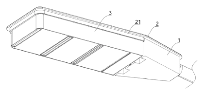
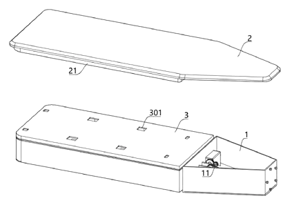
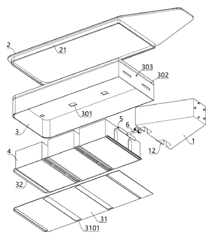
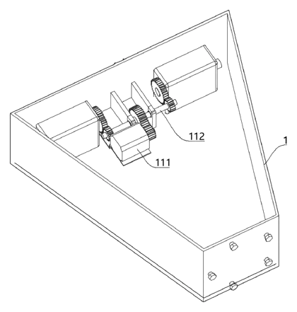
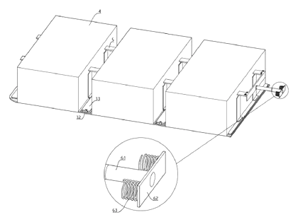
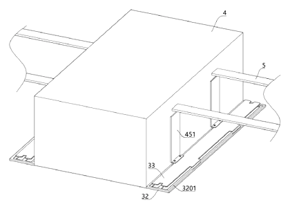
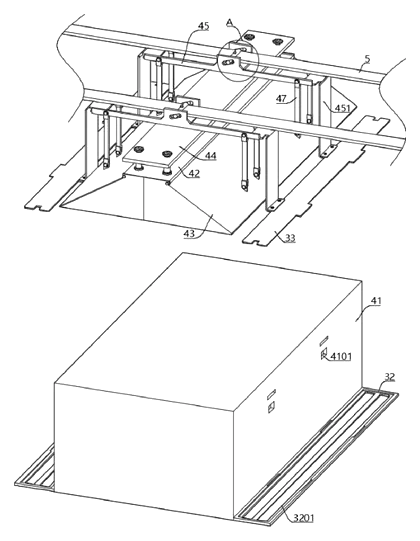
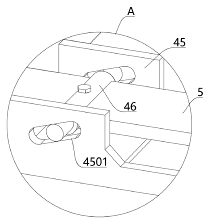
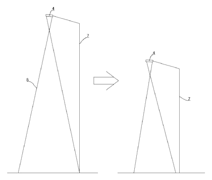
Drawings reproduced from the public patent document for reference.