
Patent CN118629815B
Updated November 5, 2026Two-Stage Safety Switch for Electric Cutting Tools
Standard single-action triggers on power tools can be accidentally activated by snagged clothing, dropped tools, or inadvertent pressure during transport. This design adds a mandatory two-step activation sequence: a user must first press a dedicated side button to mechanically disengage a lock, then pull the trigger. The lock automatically re-engages when the button is released, ensuring the tool cannot restart unless the operator intentionally repeats the unlocking step.
- China invention patent - in force
- No filings outside China
- Power tool switch mechanisms
- Plastic housing, metal pivot, spring reset elements
Splat! What let you down?
🔒
Mechanical Lockout
A rib on the trigger is physically blocked by a protrusion on the button until the button is pressed.
🔄
Auto-Reengaging
Spring-loaded button returns to the blocking position immediately upon release, securing the trigger.
🛡️
Anti-Rotation Guide
Dual annular columns with grooves keep the button aligned and prevent it from spinning in the housing.
⚙️
Interference-Free Travel
Gap width between trigger ribs exceeds button protrusion width, ensuring smooth trigger pull when unlocked.
Bring this product to market
- ✓ Patent review Patent family and legal status reviewed in the relevant jurisdictions.
- 2 Product brief · now How it works, uses and options written up
- 3 Prototype First samples for buyers to review
- 4 Pilot run Small first batch for launch customers
- 5 Volume production Repeat orders at scale
Buyer interest
– of 100 buyers needed to start prototyping
One click, no sign-up. Each vote is one real visitor, and products with the most interest go to prototyping first.
Build team: no members yet. Need a partner, co-funding or skills to build this? Join and we introduce the team once it forms.
Patent Rights & Team Participation
Before joining a development team, participants should ensure they have the necessary rights or authorization to participate in the project.
Participation is generally appropriate where:
- You own the relevant patent rights or have obtained permission or a license from the rights holder.
- The relevant patent rights have expired or have been legally invalidated in the jurisdictions where the planned activities will take place.
- The planned development, manufacturing, and commercialization activities have been independently assessed and do not infringe applicable patent rights in the relevant jurisdictions.
Important: Being located outside a country where a patent is protected does not automatically exempt you from patent infringement risks. Patent rights may apply based on where development, manufacturing, use, sale, or import activities take place.
IP2M does not grant any patent license or authorization through team participation. Joining a project does not provide permission to use, manufacture, or commercialize patented technology.
The problem
Accidental activation of handheld power tools poses significant safety risks. In many standard designs, the trigger is exposed and can be depressed if the tool is dropped, if clothing snags on the lever, or if the tool is placed down with the handle facing upward. While some tools use simple electronic delays or basic physical guards, these often lack positive mechanical confirmation that the user intended to operate the device. Furthermore, existing multi-stage switches can suffer from alignment issues where the unlocking mechanism rotates within its housing, causing inconsistent engagement with the trigger and potential failure points over time.
The solution
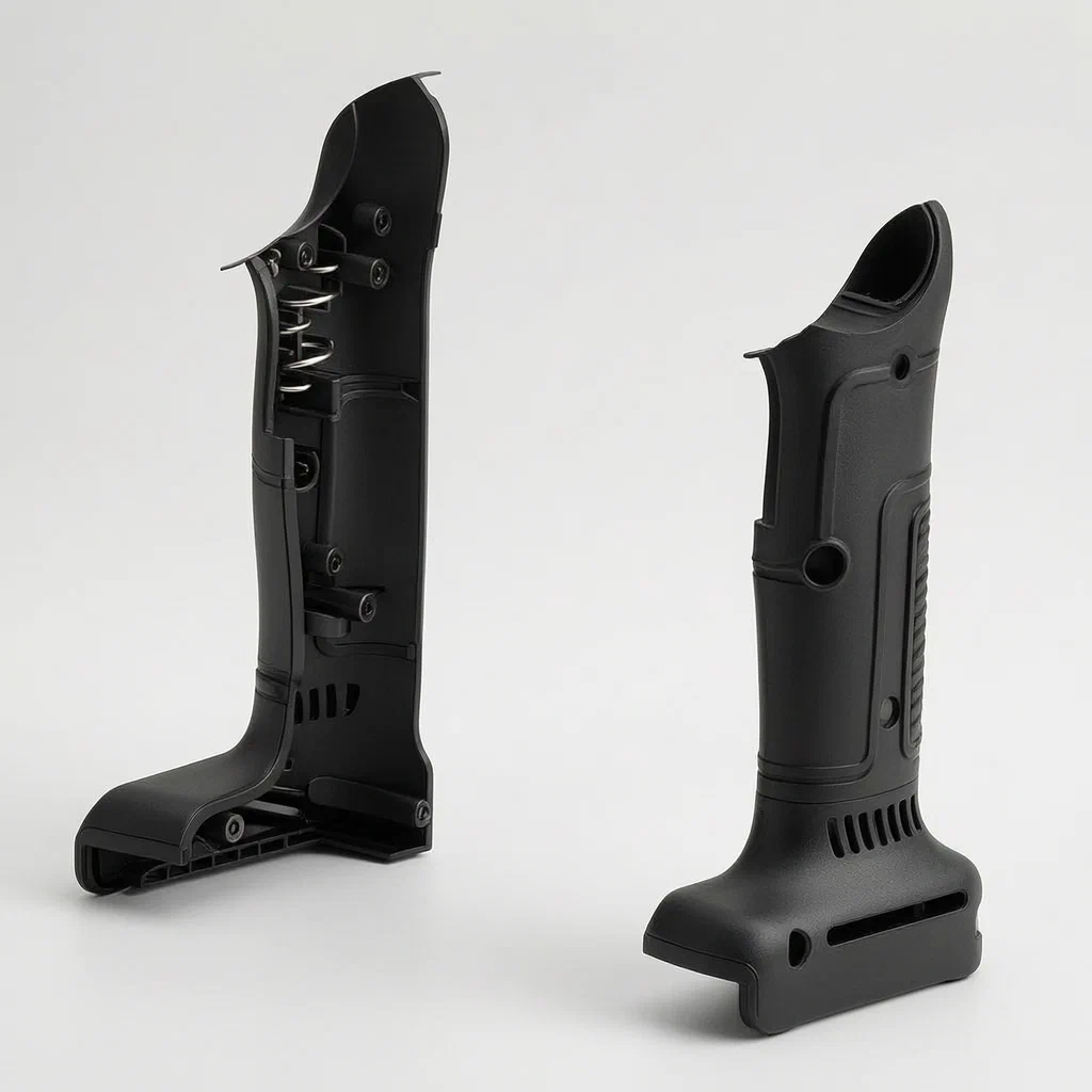
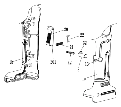
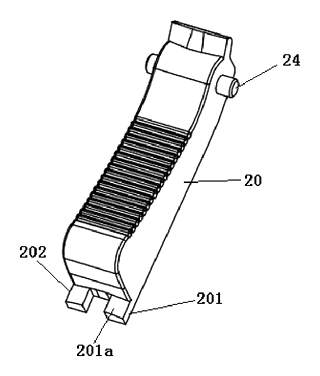
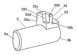
The patent describes a switch assembly integrated into a tool housing composed of two half-shells. The core solution involves a trigger (20) mounted on a pivot (24) and a separate button (3) mounted on the side of the housing.
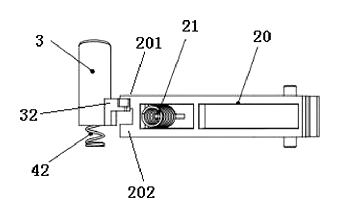
- Blocking State: When the button is in its initial position (not pressed), a protruding block (32) on the button abuts against a first convex rib (201) on the bottom of the trigger. This physical contact prevents the trigger from being pulled downward.
- Unlocking State: When an external force presses the button inward, it moves to an open position. The protruding block shifts laterally relative to the trigger’s path. Because the trigger has a second convex rib (202) spaced apart from the first, the protruding block passes through the gap between the two ribs. This clears the obstruction, allowing the trigger to be depressed.
- Locking During Operation: If the trigger is pulled while the button is held down, the tool operates. However, if the operator releases the button, the second elastic reset element (42) pushes the button back to the initial position. As it returns, the protruding block moves under the trigger’s rear end. The limiting groove (320) on the block allows the first convex rib to slide into it, but the geometry ensures that once the button resets, it effectively blocks the trigger from returning to its rest position or being re-pulled without pressing the button again. This creates a “dead man” style safety where continuous intent is required to maintain operation after the initial unlock.
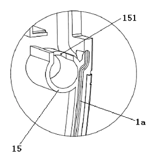
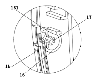
- Anti-Rotation: To ensure the button always aligns correctly with the trigger ribs, the housing features first and second annular columns (1a/1b inner walls). These columns have limiting grooves that engage with the button’s protruding block and a secondary limit block, preventing the button from rotating circumferentially as it slides in and out.
Who it is for
- Power Tool Manufacturers: Brands producing cordless cutters, saws, or shears that need to meet strict safety standards (like IEC 62841) regarding accidental start-up prevention.
- Industrial Equipment Integrators: Companies building custom automated cutting stations where manual override safety is critical.
- OEM Suppliers: Component manufacturers looking to supply pre-assembled switch modules to various hand-tool brands.
- Safety-Focused Retailers: Distributors targeting professional users who prioritize tools with positive mechanical locks over simple electronic safeguards.
How it works
The main parts
| No. | Part | What it does |
|---|---|---|
| 1 | Tool Housing | Two-piece shell (1a, 1b) containing the switch; includes anti-rotation columns. |
| 20 | Trigger | Main actuator; pivots on pin 24; has first (201) and second (202) convex ribs. |
| 3 | Button | Side-mounted unlocker; slides axially; has protruding block (32) with groove (320). |
| 21, 42 | Reset Elements | Springs that return the trigger (21) and button (42) to their initial positions. |
| 22 | Switch Member | Micro-switch inside housing; activated when trigger is fully depressed. |
| 24 | Pivot Pin | Connects trigger to housing, allowing rotational movement. |
| 13 | Through Hole | Opening in housing for the button to pass through. |
Operating steps
- Initial State: Button is out. Protruding block (32) hits first rib (201). Trigger is locked.
- Unlock: User presses button. Block moves past the gap between ribs 201 and 202.
- Activate: User pulls trigger. Trigger pivots, compresses spring 21, and activates micro-switch 22. Tool turns on.
- Deactivate/Lock: User releases button. Spring 42 pushes button back. Block (32) moves behind rib 201. If trigger was released, it springs back. If trigger was held, the block prevents further action until button is pressed again.
Applications
Electric Handheld Cutters
Used in carpet cutting or vinyl wrapping where blades are exposed. The two-stage switch prevents the blade from engaging if the tool falls onto the trigger.
Cordless Shears
For sheet metal or fabric cutting. The mechanical lock ensures the jaws do not close unexpectedly during storage or transport, protecting both the material and the user.
Industrial Hot Knives
Electrothermal cutting blades (as claimed in Claim 5) heat up rapidly. Accidental activation could cause burns or fire. This switch ensures the heater only engages when the operator deliberately performs the unlock-and-pull sequence.
Construction Site Tools
On busy sites, tools are often tossed into bags or left on scaffolding. The robust plastic housing and positive mechanical stop reduce liability compared to electronic-only solutions that might fail due to moisture or dust.
Where it is less suitable
- Continuous Duty Machines: Tools requiring constant operation without frequent stopping (e.g., stationary table saws) may find the two-stage requirement cumbersome.
- Gloved Use with Large Buttons: If the button is too small, operators wearing thick industrial gloves might struggle to press it accurately before pulling the trigger.
- High-Vibration Environments: While the anti-rotation feature helps, extreme vibration could theoretically cause premature wear on the sliding interface if tolerances are not tight.
Patent & Production
At a glance
| Patent number | CN118629815B (application CN202411096179) |
| Type | China invention patent (发明专利) - protects method and product structure |
| Original title | Switch structure of electric tool and electrothermal cutting blade (电动工具的开关结构及其电热割刀) |
| Patent owner | Jinhua Jinshun Tools Co Ltd |
| Inventors | Zhou Suhu, Hu Jianlin, Fan Qinjian, Yu Chenjian |
| Filing date | 2024-08-12 |
| Grant date | 2024-11-05 |
| Status (China) | In force until at most 2044-08-12 (if annual fees are paid) |
| Patent family | Public record shows Chinese filings only - no US, European, Japanese, PCT or other filings listed |
| Cited by | 0 later documents |
| Source | Google Patents (search for CN118629815B) |
What the claims cover, in plain language
Claim 1 defines a switch structure comprising a tool housing, a trigger with a first elastic reset element, and a switch member. Key feature: a button with a second elastic reset element is arranged on the housing. The button has a second limiting part (protruding block with a groove) that interacts with a first limiting part (convex rib) on the trigger. In the initial position, the block abuts the rib, blocking the trigger. When pressed, the block offsets, allowing the trigger to move. Upon release of the button, the block re-abuts the rib to prevent the trigger from resetting freely or being pulled again without unlocking. Specific geometric details include the gap between two ribs on the trigger being wider than the button’s block.
Claim 2 adds an anti-rotation structure to prevent the button from spinning.
Claim 3 details the anti-rotation structure: cylindrical button, protruding block near the far end, and a limit block connected to it. The housing has two annular columns with grooves that engage these blocks.
Claim 4 specifies the switch member is a micro switch.
Claim 5 extends protection to an electrothermal cutting blade incorporating this switch structure.
This is a simplified reading for orientation only. The legal scope is defined by the exact claim wording in the official Chinese document.
What this means for US production
This patent was filed in China and is currently in force. Making or selling this specific switch configuration in China requires the owner’s permission. The public record shows no US or other foreign counterpart.
Two points to settle early:
- Other patents may exist. Power tool safety switches are a dense field with numerous US patents covering similar two-stage mechanisms, electronic locks, and ergonomic button placements. A freedom-to-operate (FTO) review is strongly recommended to identify any conflicting US utility patents before mass production.
- Design-around feasibility. The specific geometric interaction (rib widths, groove shapes) described in Claim 1 is narrow. Altering the locking interface (e.g., using a different shape or electronic sensing instead of pure mechanical abutment) may avoid infringement, but requires engineering validation.
Customization and manufacturing
What can be customized
| Area | Options |
|---|---|
| Housing Material | Glass-filled nylon (standard for impact resistance) or ABS blends. |
| Button Color/Texture | Soft-touch rubber overmolding for grip; color coding for safety. |
| Trigger Geometry | Rib height and gap width can be adjusted based on spring rates. |
| Switch Type | Standard micro-switch, or a Hall-effect sensor if a non-contact option is preferred. |
| Mounting | Screw hole patterns for integration into various tool chassis. |
Things to plan for (US market)
- UL 62841 / IEC 62841: Standard for motor-operated electric tools. Safety switches must withstand specified cycle tests and environmental conditions.
- OSHA Requirements: General duty clause implies tools should have adequate guarding; this switch aids compliance but doesn’t replace blade guards.
- Proposition 65: Ensure plastics and metals used in the housing and trigger do not contain restricted chemicals (lead, cadmium, etc.).
How a project runs
- Inquiry - Define tool class, voltage, and target safety rating.
- Design - CAD modeling of rib/groove interaction; tolerance analysis for anti-rotation columns.
- Prototype - 3D-printed housings for fit check; machined triggers for functional testing.
- Testing - Cycle life testing (trigger/button actuation); drop tests; thermal cycling.
- Production - Injection molding for housing/button/trigger; assembly of springs and switch.
Quantities & timeline
Injection molds for the three-part housing and button assembly are the primary cost driver. Tooling lead times typically range from 8-12 weeks depending on mold complexity. Send us your tool specifications, volume estimates, and safety certification requirements and we will reply with options.
Patent drawings
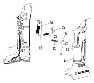
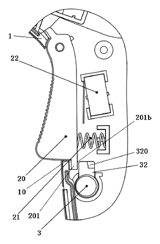
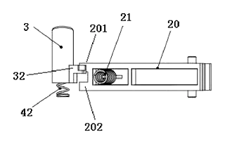
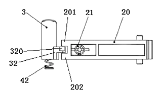
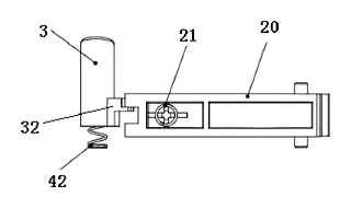
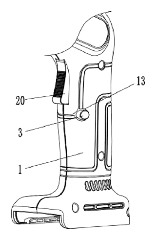
Drawings reproduced from the public patent document for reference.
Production notes
Tooling and process
The housing components likely require glass-filled nylon injection molding to withstand impact and heat. The trigger and button need precise mold cavities to ensure the rib and groove interactions function smoothly. Metal pivot pins may be press-fit or secured with rivets.
Cost drivers
Mold complexity for the anti-rotation columns and the intricate ribbing on the trigger typically drives tooling costs. Assembly steps involving multiple springs and delicate alignment of the button add labor time. Surface finish requirements for the button grip area also impact cost.
Prototyping path
Prototyping typically starts with 3D-printed housings to verify the overall fit and screw hole locations. Machined aluminum or steel samples for the trigger and button allow testing of the mechanical lock strength and travel distance before committing to expensive injection molds.
What we would change before tooling
We would likely verify the clearance between the button block and the trigger ribs under load. Tighten tolerances on the anti-rotation grooves to prevent wobble. Consider adding a soft-touch overmold to the button surface for better ergonomics and slip resistance.
Common failure points
Spring fatigue is a risk if the reset force is too high or materials degrade. Pivot pin wear can lead to loose trigger action. The button may jam if debris enters the anti-rotation column interface. Heat transfer from the tool motor could warp plastic components if thermal clearance is insufficient.
Frequently asked questions
How does the safety lock actually work?
It is a mechanical interlock. The trigger has a raised rib that hits a block on the side button. When the button is out (initial position), the block stops the trigger from moving. You must push the button in to move the block away, creating a gap that lets the trigger pivot.
Does the tool stay on if I let go of the button?
No. The button is spring-loaded. If you release the button, it snaps back to the initial position. Depending on the exact timing, the block returns to a position that either prevents the trigger from being pulled again or locks it in place until the next deliberate unlock sequence. This prevents accidental restarts.
Can the button rotate inside the housing?
No. The patent describes an anti-rotation structure. The button has specific protrusions that slide into grooves formed by annular columns inside the tool housing. This keeps the button perfectly aligned with the trigger ribs every time you press it.
Is this switch compatible with all power tools?
The structure is designed for handheld tools like cutters and shears. It can be adapted for other tools, but the housing dimensions, trigger pivot point, and button placement must be customized to fit the specific tool chassis.
What materials are used for the switch?
The patent does not specify housing materials. Production can choose an impact-resistant plastic such as glass-filled nylon, with molded plastic for the trigger and button, metal for the pivot pin and springs, and a standard micro-switch as the switch member.
How long does the mechanism last?
Durability depends on the spring quality, plastic wear, and lubrication. The patent does not state a cycle life; life testing on prototypes is required to confirm performance for a specific application.
Can this design be made and sold in the US?
The patent is currently in force in China. The public record shows no US counterpart, so it does not restrict the design in the US. However, other US patents may cover similar safety switch concepts. We recommend a freedom-to-operate review before launching in the US market.
Are you affiliated with the patent owner?
No. IP2M is an independent design and manufacturing service working from the public patent document.
Request a quote
Click Request a Quote below to see our email address - copy it, or open your email app with a ready-made message. Please mention patent CN118629815B in the subject.
Helpful details to include:
- Your company and channel (tool manufacturer, OEM integrator, safety equipment supplier)
- Tool type (cutter, shear, hot knife, etc.)
- Voltage/Power requirements for the switch component
- Customization needs (color, button size, housing modifications)
- Estimated quantity and target price
- Timeline - when you would like prototypes and the first shipment
You can also reach us at (332) 203-9997.
Page editor: Daniel Chen, Product Research Editor · IP2M
Last updated November 5, 2026. If something on this page looks wrong, email [email protected] and we will check it against the patent.
Interested in building this?
Tell us your target market, quantity and timeline. We reply with options for prototyping, small-batch runs or volume production.
Send your inquiry to
Please put CN118629815B in the subject line and tell us your company, country, estimated quantity and timeline.
Prefer to talk? Call (332) 203-9997.
More product-ready patents
All Tools & Workshop patents →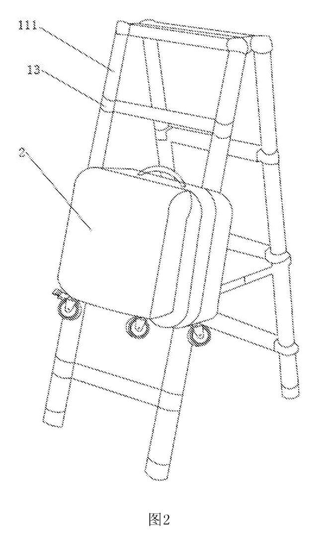
Tools & Workshop
Rolling Tool Box with Telescoping Step Ladder
Telescoping A-frame ladder with an attached rolling tool box that slides to your working height.
Patent CN206290197U
Tools & Workshop
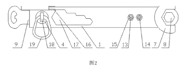
Folding 3-Handle Wrench Multi-Tool
Folding three-handle wrench multi-tool with magnetic screwdriver bits, saw, file and bottle opener.
Patent CN205290875U
Tools & Workshop
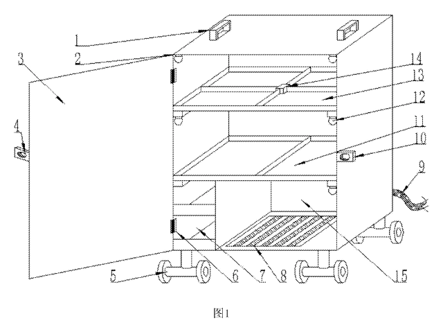
Rolling Auto-Repair Tool Cabinet with Built-In Lights
Lockable rolling tool cabinet for car repair with interior lights, a lubricant tray, parts drawers and a tool bay.
Patent CN205989314U
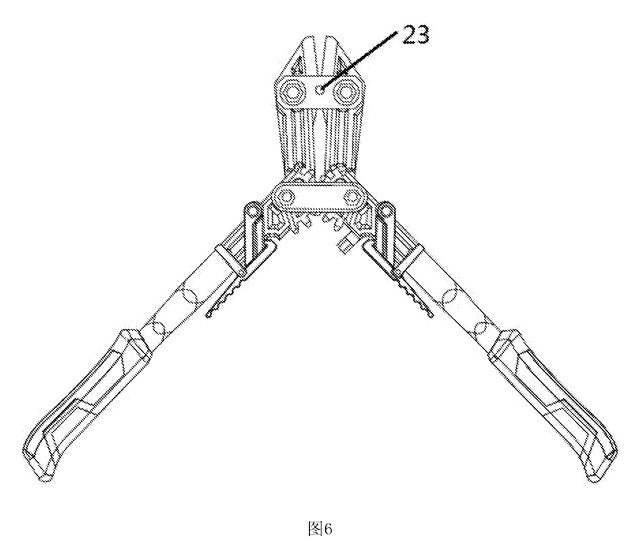
Tools & Workshop
Wide-Opening Folding Bolt Cutter
Bolt cutter with linked, gear-meshing handles that open up to 190° and fold in half for storage.
Patent CN207206226U
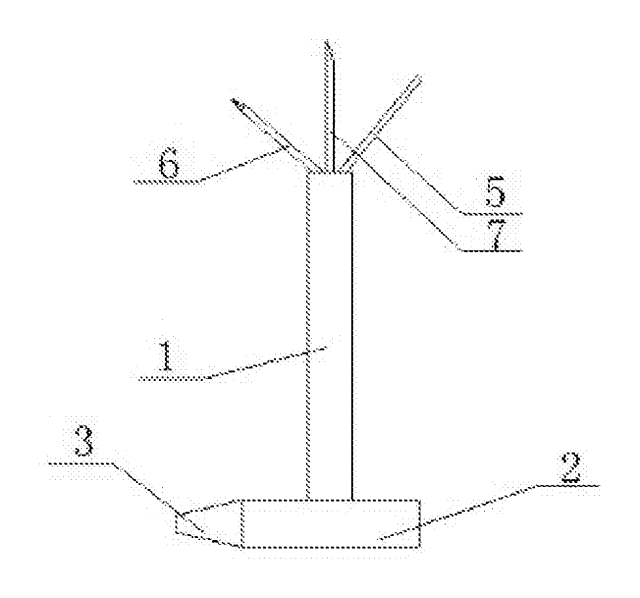
Tools & Workshop
Nail-Holding Hammer with Fold-Out Drivers
Hammer with a nail-holding T-slot in the head and fold-out drivers stored in the handle.
Patent CN205254927U
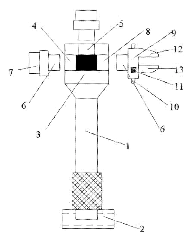
Tools & Workshop
Modular Wrench with Screw-On Heads
Wrench handle with a three-way threaded hub for screw-on adjustable and hex heads, plus a pipe sleeve.
Patent CN206216564U
Browse by category
- Apparel & Accessories (39)
- Baby & Kids (26)
- Bags & Luggage (15)
- Bath & Personal Care (26)
- Car Accessories (21)
- Furniture, Bedding & Storage (21)
- Garden & Outdoor (29)
- Health & Wellness (12)
- Home, Kitchen & Cleaning (43)
- Lighting (20)
- Packaging & Containers (10)
- Pet Products (10)
- Phone & Camera Accessories (8)
- Retail Display (22)
- School, Office & Art (30)
- Sports & Recreation (39)
- Tools & Workshop (48)
- Toys & Games (20)
This page is based on the public patent document CN118629815B, assigned to Jinhua Jinshun Tools Co Ltd. IP2M is an independent manufacturing service and is not affiliated with, endorsed by or licensed by the patent owner. Images marked as concept renderings are illustrations, not photos of an existing product. Patent status information is provided for reference only and is not legal advice; confirm freedom to operate for your market before production. Full disclaimer.