
Patent CN118636095B
Updated October 29, 2026Adjustable Suction-Cup Jig for Furniture Cabinet Assembly
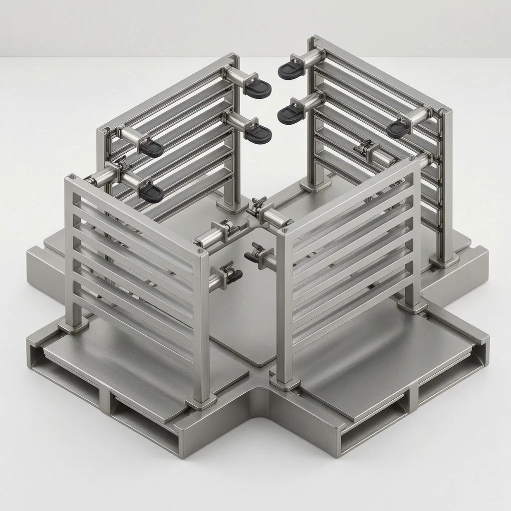
Holding wood panels steady while screwing a cabinet box together usually takes two workers or a pile of clamps that get in the way. This device uses a cross-shaped base with sliding supports to position multiple connection points across different panel sizes. At each point, a connecting column carries four small air pressure pipes. When you press the assembly against a wood panel, a fitting board pushes a piston inside the pipe. That movement pulls air through a central communicating frame and an outlet pipe into a suction cup, which grips the panel surface. Sliding blocks let you shift the columns up and down or side to side, so the same jig fits narrow drawer boxes and wide wardrobe sides without changing tools.
- China invention patent - in force
- No filings outside China
- Furniture assembly tooling
- Pneumatic suction, sliding adjustment
Splat! What let you down?
🔲
Cross-shaped base
The main body is a cross shape with symmetrical transverse and vertical grooves linked by a movable groove.
↕️
Two-axis adjustment
Sliding blocks move between height adjusting grooves and width adjusting grooves to position the columns.
💨
Mechanical vacuum
Pressing the fitting board drives a piston that creates suction in four cups per column, no pump needed.
🔒
Threaded lock
A fixing block with a threaded rod secures the slide bar once the column is in position.
Bring this product to market
- ✓ Patent vetted China-only family and legal status checked
- 2 Product brief · now How it works, uses and options written up
- 3 Prototype First samples for buyers to review
- 4 Pilot run Small first batch for launch customers
- 5 Volume production Repeat orders at scale
Buyer interest
– of 100 buyers needed to start prototyping
One click, no sign-up. Each vote is one real visitor, and products with the most interest go to prototyping first.
Build team: no members yet. Need a partner, co-funding or skills to build this? Join and we introduce the team once it forms.
The problem
Assembling flat-pack or custom cabinet boxes requires holding several wood panels at exact right angles while fasteners are driven. Workers typically use bar clamps, corner clamps, or rely on a second person to keep the pieces square. Clamps leave marks on finished surfaces, take time to reposition when panel sizes change, and often block the path of a drill or screwdriver. For shops building cabinets in varying dimensions, resetting a dedicated fixture for every new size slows production.
The solution
This device replaces external clamps with an adjustable frame and built-in mechanical suction.
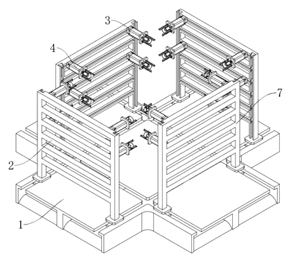
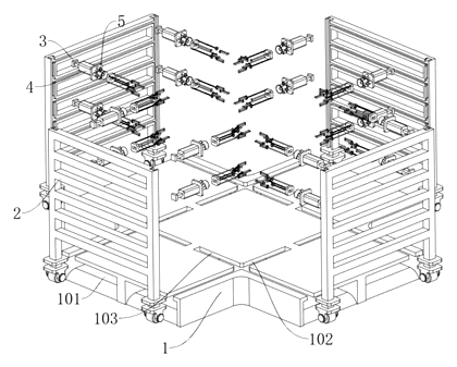
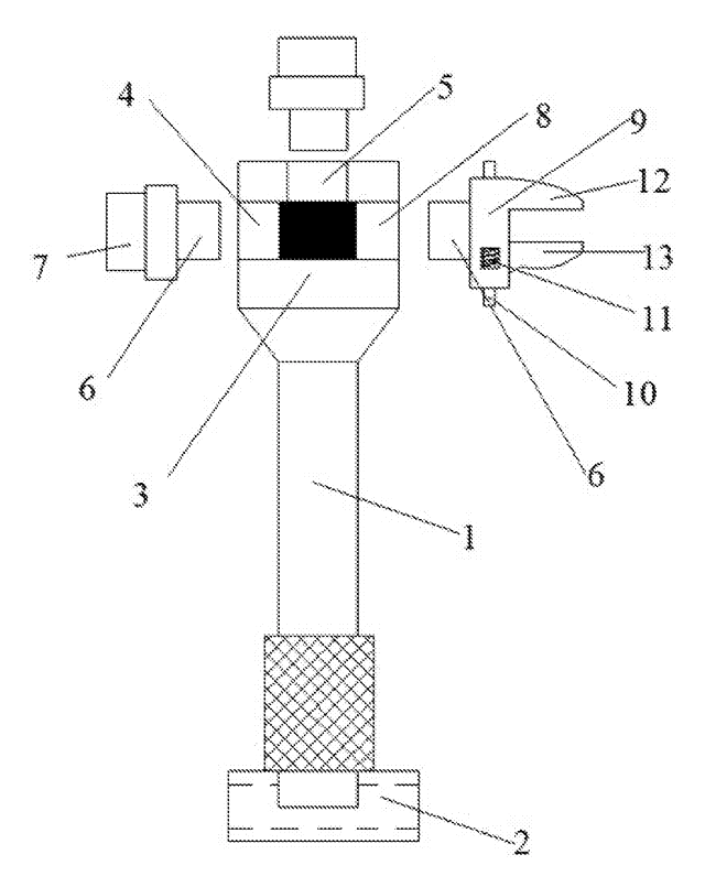
- A main body (1) shaped as a cross has transverse grooves (102) and vertical grooves (103) connected by a movable groove (101).
- A supporting mechanism (2) slides into the groove via a limiting sliding frame (201), raising a vertical rod (203) and a cross rod (204).
- A connecting mechanism (3) rides on the rods. A sliding block (301) moves through a height adjusting groove (205) and into a width adjusting groove (206) to set the position of a connecting column (303).
- An adsorption mechanism (5) on the column uses four air pressure pipes (502) linked by a communicating frame (501) to an air outlet pipe (504) and a suction cup (505).
- A pressing mechanism (6) inside each pipe contains a spring (601), a piston (602), a depression bar (603), a fitting board (604) and a push rod (605) stopped by a spacing ring (606) against an abutting ring (503).
- A fixing mechanism (4) with a fixing block (401) and threaded rod (404) locks the slide bar (302) in place.
Who it is for
- Custom cabinet shops that build boxes in varying widths and heights daily and need one jig instead of many fixed fixtures.
- RTA furniture manufacturers looking for a repeatable way to hold panels square during manual or semi-automated assembly lines.
- Woodworking tool brands seeking a clamp-free panel-holding product to add to their assembly accessory catalog.
- Contract furniture installers who assemble units on site where large bench clamps are impractical.
How it works
The main parts
| No. | Part | What it does |
|---|---|---|
| 1 | Main body | Cross-shaped base with transverse grooves (102), vertical grooves (103) and movable groove (101). |
| 2 | Supporting mechanism | Limiting sliding frame (201), vertical rod (203) and cross rod (204). |
| 3 | Connecting mechanism | Sliding block (301), slide bar (302), connecting column (303) with threaded holes (304) and through holes (305). |
| 4 | Fixing mechanism | Fixing block (401) with sliding hole (402) and threaded rod (404) to lock the slide bar. |
| 5 | Adsorption mechanism | Communicating frame (501), air pressure pipes (502), abutting rings (503), air outlet pipe (504) and suction cups (505). |
| 6 | Pressing mechanism | Spring (601), piston (602), depression bar (603), fitting board (604), push rod (605) and spacing ring (606). |
| 7 | Transverse frame | Works with the supporting mechanisms (mentioned in description). |
Operating steps
- Set the width. Slide the limiting sliding frame (201) along the transverse groove (102) to match the panel width.
- Set the height. Pull the sliding block (301) out of the width adjusting groove (206), move it up or down the height adjusting groove (205), and push it into the correct width adjusting groove on another cross rod (204).
- Lock the position. Tighten the threaded rod (404) on the fixing block (401) against the slide bar (302).
- Attach the panel. Press the wood panel against the fitting boards (604). The push rod (605) drives the piston (602) inward against the spring (601), drawing air from the suction cups (505) through the communicating frame (501). The cups grip the panel.
- Release. Pull the panel away; the spring returns the piston, breaking the vacuum.
Applications
Custom cabinet assembly
A shop building kitchen cabinets in different widths sets the sliding blocks once per box size. The suction cups hold the side panels square to the base while screws go through the pre-drilled holes, removing the need for a helper.
RTA furniture packing lines
Workers assembling knock-down wardrobes place the panels onto the jig. The mechanical vacuum activates instantly on contact, keeping pieces aligned while cam locks or dowels are inserted.
Drawer box gluing
Small drawer sides are difficult to clamp without squeezing out all the glue. The adjustable columns fit narrow dimensions, and the suction cups apply even holding pressure without marring the wood surface.
On-site installation
Installers assembling shelving units in tight rooms cannot swing long bar clamps. The compact cross base sits on a workbench or floor, and the panels snap onto the suction cups for fastening.
Where it is less suitable
- Curved or heavily textured panels. Suction cups require a relatively smooth, flat surface to seal; rough-sawn lumber or carved faces will leak air.
- Continuous automated presses. High-speed CNC assembly cells typically use integrated pneumatic clamps built into the machine bed rather than standalone jigs.
- Very heavy solid-wood slabs. The device is described for furniture cabinet bodies; thick countertop slabs may exceed the holding capacity of the mechanical suction cups, which is to be confirmed in design.
Frequently asked questions
How do the suction cups work without a vacuum pump?
Each connecting column has four air pressure pipes. When you press a wood panel against the fitting board, it pushes a piston inside the pipe against a spring. That movement draws air out of the suction cup through a communicating frame and an outlet pipe, creating a mechanical vacuum that holds the panel. Releasing the pressure lets the spring return the piston and breaks the seal.
What size panels can this jig hold?
The patent describes sliding blocks that move between height adjusting grooves and width adjusting grooves to accommodate different sizes. Exact maximum and minimum panel dimensions are set in design based on the length of the cross rods and the travel of the grooves.
Can I adjust the jig for different cabinet depths?
Yes. The supporting mechanism slides along transverse grooves in the cross-shaped main body, and the limiting sliding frame moves through a movable groove that connects the transverse and vertical grooves. This allows positioning the columns at various points across the base.
Will the suction cups scratch finished wood?
The patent specifies suction cups but does not detail the rubber compound. In production, soft silicone or non-marking rubber cups are selected to protect melamine, veneer or painted surfaces. Cup material is confirmed on prototypes.
How is the column locked in place after adjusting?
A fixing mechanism slides on the outer wall of the slide bar. It includes a fixing block with a threaded rod. Once the sliding block is positioned in the desired width adjusting groove, tightening the threaded rod secures the assembly.
Does it work on rough-sawn lumber?
The suction cups require a surface smooth enough to form an air seal. Rough, porous or heavily textured wood will likely leak air and reduce holding force. Smooth plywood, MDF, melamine and finished boards are the intended surfaces.
Can this design be made and sold in the US?
The patent was filed only in China and is in force there until at most 2044-08-16 (if annual fees are paid). It has no US counterpart, so it does not restrict manufacturing or sales in the United States. However, similar panel-holding jigs may be covered by other US patents - see Patent & Production - so we recommend a freedom-to-operate check before volume production.
Are you affiliated with the patent owner?
No. IP2M is an independent design and manufacturing service working from the public patent document.
Request a quote
Click Request a Quote below to see our email address - copy it, or open your email app with a ready-made message. Please mention patent CN118636095B in the subject.
Helpful details to include:
- Your company and channel (cabinet shop, RTA brand, tool distributor, installer)
- Target panel sizes (minimum and maximum width, height and thickness)
- Panel surface types (melamine, raw wood, painted, veneer)
- Preferred base material (aluminum, steel, etc.)
- Estimated quantity and target price
- Timeline - when you would like prototypes and the first shipment
You can also reach us at (332) 203-9997.
Explore this product
Interested in building this?
Tell us your target market, quantity and timeline. We reply with options for prototyping, small-batch runs or volume production.
Send your inquiry to
Please put CN118636095B in the subject line and tell us your company, country, estimated quantity and timeline.
Prefer to talk? Call (332) 203-9997.
More product-ready patents
All Tools & Workshop patents →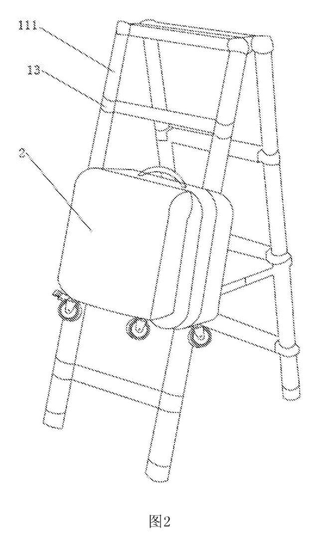
Tools & Workshop
Rolling Tool Box with Telescoping Step Ladder
Telescoping A-frame ladder with an attached rolling tool box that slides to your working height.
Patent CN206290197U
Tools & Workshop
Folding 3-Handle Wrench Multi-Tool
Folding three-handle wrench multi-tool with magnetic screwdriver bits, saw, file and bottle opener.
Patent CN205290875U
Tools & Workshop
Rolling Auto-Repair Tool Cabinet with Built-In Lights
Lockable rolling tool cabinet for car repair with interior lights, a lubricant tray, parts drawers and a tool bay.
Patent CN205989314U
Tools & Workshop
Wide-Opening Folding Bolt Cutter
Bolt cutter with linked, gear-meshing handles that open up to 190° and fold in half for storage.
Patent CN207206226U
Tools & Workshop
Nail-Holding Hammer with Fold-Out Drivers
Hammer with a nail-holding T-slot in the head and fold-out drivers stored in the handle.
Patent CN205254927U
Tools & Workshop
Modular Wrench with Screw-On Heads
Wrench handle with a three-way threaded hub for screw-on adjustable and hex heads, plus a pipe sleeve.
Patent CN206216564U
Browse by category
- Apparel & Accessories (22)
- Baby & Kids (16)
- Bags & Luggage (9)
- Bath & Personal Care (16)
- Car Accessories (10)
- Furniture, Bedding & Storage (12)
- Garden & Outdoor (18)
- Health & Wellness (8)
- Home, Kitchen & Cleaning (24)
- Lighting (12)
- Packaging & Containers (6)
- Pet Products (6)
- Phone & Camera Accessories (4)
- Retail Display (13)
- School, Office & Art (19)
- Sports & Recreation (25)
- Tools & Workshop (27)
- Toys & Games (12)
This page is based on the public patent document CN118636095B, assigned to Koomo Home Furnishing Manufacturing Co Ltd Shandong Co. IP2M is an independent manufacturing service and is not affiliated with, endorsed by or licensed by the patent owner. Images marked as concept renderings are illustrations, not photos of an existing product. Patent status information is provided for reference only and is not legal advice; confirm freedom to operate for your market before production. Full disclaimer.