At a glance
| Patent number | CN118636095B (application CN202411127176) |
| Type | China invention patent (发明专利) - protects product shape, structure and method |
| Original title | Auxiliary connection device for mounting furniture cabinet body (一种家具柜柜体安装用辅助连接装置) |
| Patent owner | Koomo Home Furnishing Manufacturing Co Ltd Shandong Co |
| Inventors | Dong Ruijun |
| Filing date | 2024-08-16 |
| Grant date | 2024-11-05 |
| Status (China) | In force in China until at most 2044-08-16 (if annual fees are paid) |
| Patent family | Chinese filings only - no US, European, Japanese, PCT or other filings listed |
| Cited by | 0 later documents |
| Source | Google Patents (search for CN118636095B) |
What the claims cover, in plain language
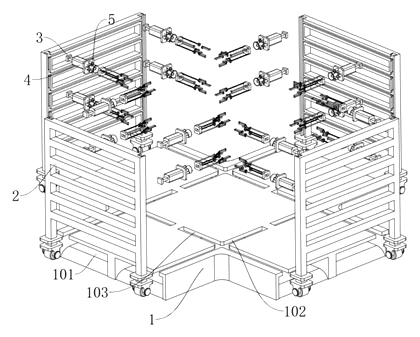
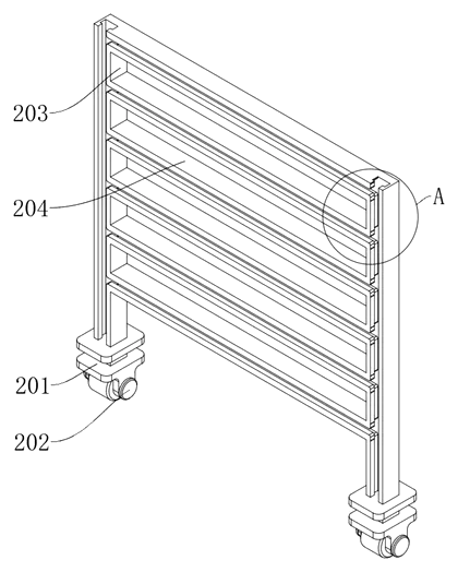
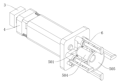
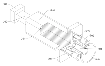
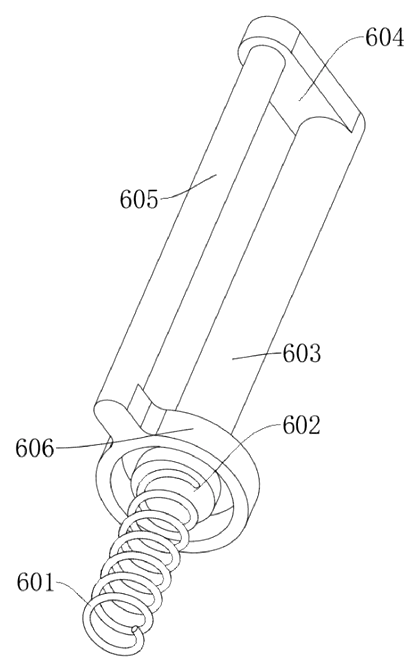
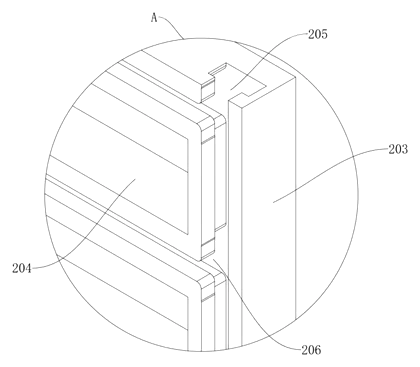
Claim 1 covers an auxiliary connection device for furniture cabinet installation comprising a main body (1) with a transverse groove (102) at its top. A supporting mechanism (2) includes a limiting sliding frame (201) sliding in a movable groove (101), carrying a vertical rod (203) and a cross rod (204). A connecting mechanism (3) on the cross rod has a slide bar (302) sliding on the vertical rod and a connecting column (303). An adsorption mechanism (5) on the column includes a communicating frame (501) linked to four air pressure pipes (502) arranged in a circumferential array. A pressing mechanism (6) inside each pipe uses a spring (601) and piston (602) connected to a depression bar (603), fitting board (604), push rod (605) and spacing ring (606) that rests against an abutting ring (503). Air flows from the pipes through the frame into an air outlet pipe (504) and a suction cup (505).
Claim 2 adds that the main body is cross-shaped, with two groups of transverse grooves and two groups of vertical grooves (103) symmetrically distributed and staggered, all communicating through the movable groove.
This is a simplified reading for orientation only. The legal scope is defined by the exact claim wording in the official Chinese document.
What this means for US production
This patent was filed only in China and is currently in force there, meaning making or selling this exact device in China needs the owner’s permission. It has no US or other foreign counterpart.
Two points to settle early:
- Other patents may exist. Panel-holding jigs, vacuum clamps and adjustable assembly fixtures are covered by various US and international patents held by woodworking tool companies, so a freedom-to-operate (FTO) review of the sliding adjustment and mechanical suction features is recommended before launching in the US market.
- Suction cup material and sealing. The vacuum depends on the seal between the cup and the panel surface; cup durometer, lip profile and pipe volume must be matched to the target panel finishes, which should be set in design and confirmed on prototypes.
Customization and manufacturing
What can be customized
| Area | Options |
|---|---|
| Base size | Overall span of the cross body to fit specific cabinet ranges |
| Groove layout | Number of transverse and vertical grooves for more connection points |
| Column travel | Length of the height and width adjusting grooves |
| Suction cups | Diameter and rubber compound for smooth, melamine or veneer panels |
| Pipe count | Four per column as described, or adjusted for larger/smaller cups |
| Materials | Aluminum extrusion or steel plate for the base; POM or steel for sliders |
| Finish | Powder coating, anodizing or zinc plating for workshop environments |
Things to plan for (US market)
- General Product Safety. Hand tools and workshop jigs sold to consumers or professionals fall under CPSC jurisdiction for defects and sharp edges.
- California Prop 65. Metal finishes, rubber suction cups and plastic sliders must be screened for listed chemicals if sold in California.
- Packaging and labeling. If sold retail, instructions must clearly explain the mechanical vacuum operation to prevent misuse.
How a project runs
- Inquiry - target panel sizes, weight range, materials and quantity.
- Design - CAD modeling of the cross body, groove profiles, slider geometry and pipe/cup volumes.
- Prototype - machined or 3D-printed samples to test sliding friction, suction hold time and release action.
- Pilot run - tooling for the base and injection molds for sliders and cups; assembly of pilot units for workshop trials.
- Production - die casting or stamping of the base, machining of grooves, molding of plastic/rubber parts, final assembly and inspection.
Quantities & timeline
The cross-shaped main body requires either a die-cast mold or progressive stamping dies depending on the chosen metal. The sliding blocks, fixing mechanisms and communicating frames need precision injection molds, and the suction cups require rubber or silicone compression molds. Vacuum performance and slider wear testing take the bulk of the validation phase. Send us your target panel dimensions, required holding force, preferred materials, estimated order quantity and timeline, and we will reply with options.
Patent drawings
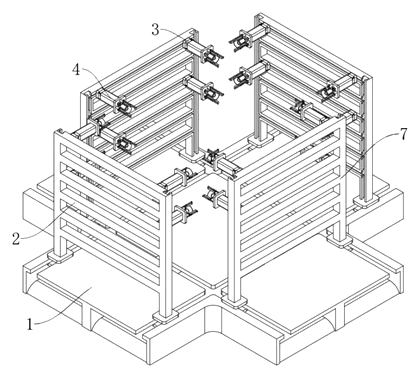
Drawings reproduced from the public patent document for reference.