
Patent CN118636096B
Updated October 26, 2026Automobile Transmission Belt Dismounting Device with Prying Mechanism
Removing an automobile transmission belt often means reaching deep into a crowded engine bay, where hands and standard wrenches collide with hoses, brackets, and hot surfaces. This dismounting device changes the geometry of the job. It attaches directly to the pulley's mounting bolt using a detachable socket sleeve, then uses a series of V-shaped prying plates to walk the belt off the pulley evenly. The prying plates are pushed outward by sliding rods housed in fixed cylinders on a rotating drive plate. A central worm, turned by a control knob on the handle, drives a linked prying mechanism that moves the plates together. Bevel gears and adjusting screws set the rod positions. Because the handle extends perpendicular to the drive plate, the entire operation happens outside the engine compartment, keeping the mechanic clear of tight spaces and moving parts.
- China invention patent - in force
- No filings outside China
- Automotive maintenance tools
- Steel handle, socket sleeve, bevel gears, V-shaped prying plates
Splat! What let you down?
🔧
Detachable socket sleeve
Fits the pulley's mounting bolt; swapped out for different vehicle models to keep one handle universal.
⚙️
Bevel gear adjustment
An input bevel gear turns multiple output bevel gears, each threaded to a sliding rod for even positioning.
↕️
Worm-driven prying
A control knob turns a worm that engages a guide rod, driving linked sliding blocks and control rods to pivot the V-shaped prying plates.
🛡️
Outside-the-bay operation
The handle stands perpendicular to the drive plate, letting the mechanic stay clear of the engine compartment during removal.
Bring this product to market
- ✓ Patent vetted China-only family and legal status checked
- 2 Product brief · now How it works, uses and options written up
- 3 Prototype First samples for buyers to review
- 4 Pilot run Small first batch for launch customers
- 5 Volume production Repeat orders at scale
Buyer interest
– of 100 buyers needed to start prototyping
One click, no sign-up. Each vote is one real visitor, and products with the most interest go to prototyping first.
Build team: no members yet. Need a partner, co-funding or skills to build this? Join and we introduce the team once it forms.
The problem
Replacing an automobile transmission belt requires loosening tension and guiding the belt off the pulleys. In modern engine bays, components are packed tightly together. Mechanics must reach past wiring harnesses, coolant hoses, and structural brackets to access the belt path. Standard pry bars or screwdrivers used to lever the belt off can slip, damaging adjacent parts or injuring the user’s knuckles against hot metal. Furthermore, applying uneven force around the pulley circumference can twist or pinch the belt, making it difficult to slide free without excessive pulling. The confined space also limits the size and angle of the tools a technician can swing, turning a routine replacement into a slow, awkward task.
The solution
This device addresses the clearance and leverage problems by anchoring directly to the pulley and doing the prying mechanically.
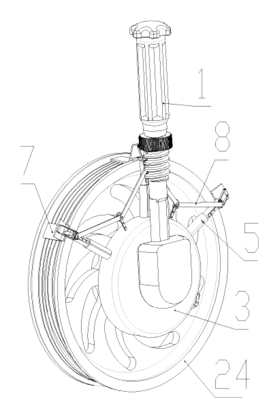
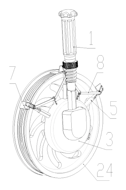
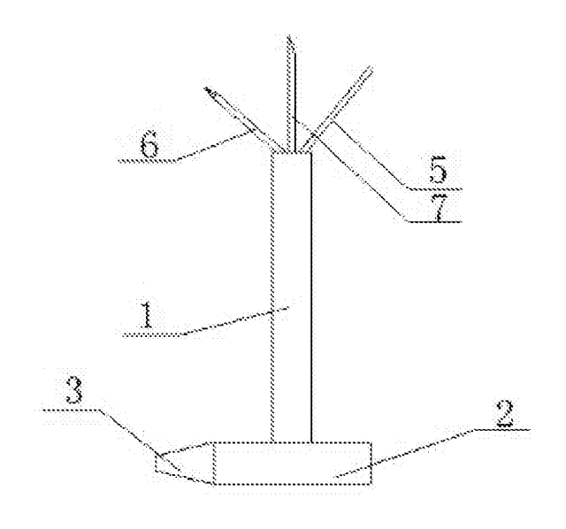
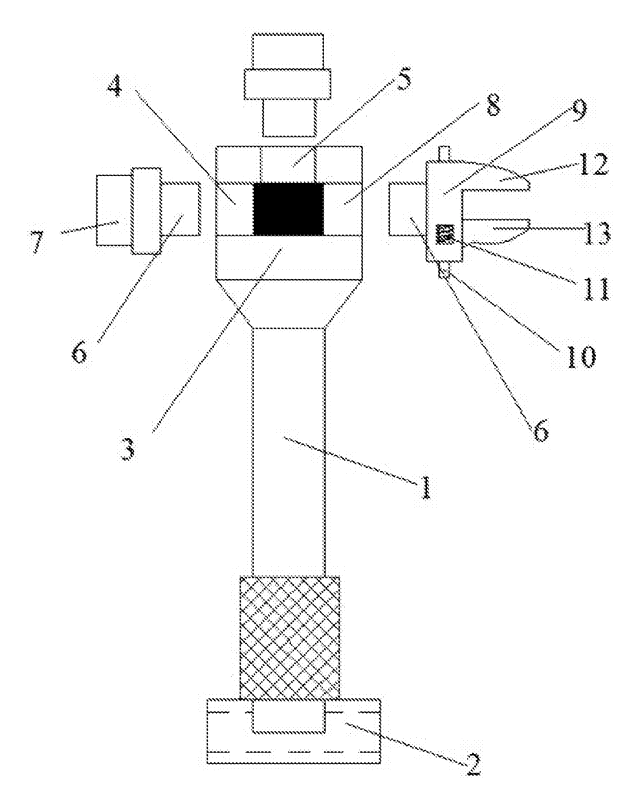
- A disassembly handle (1) connects to the target pulley (24) via a disassembly sleeve (2), which acts as a socket spanner fitting over the pulley’s mounting bolt.
- A drive plate (3) rotates on the end of the handle closest to the sleeve. The handle is positioned perpendicular to the axis of the drive plate.
- A circular boss (4) is fixed to the drive plate, carrying at least three fixed cylinders (5).
- A sliding rod (6) slides inside each fixed cylinder. At the outer end of each rod, a V-shaped prying plate (7) is rotatably mounted.
- A prying mechanism (8) coordinates the movement of these plates to lift the belt evenly off the pulley flange.
Who it is for
- Automotive tool brands expanding their specialty service equipment lines with dedicated belt removal devices rather than generic pry bars.
- Auto repair shop chains and wholesalers buying maintenance tools in bulk for technicians who service a wide range of passenger vehicles daily.
- Fleet maintenance departments managing buses, delivery trucks, or municipal vehicles where minimizing downtime during belt replacements reduces operating costs.
- Vocational training programs teaching automotive technology, where a structured mechanical tool helps students understand belt routing and safe removal procedures.
How it works
The main parts
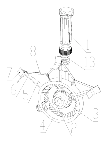
| No. | Part | What it does |
|---|---|---|
| 1 | Disassembly handle | Main body held by the operator; sits perpendicular to the drive plate. |
| 2 | Disassembly sleeve | Socket spanner that fits the pulley’s mounting bolt; detachable for different sizes. |
| 3 | Drive plate | Rotates on the handle end; carries the boss and gear train. |
| 4 | Circular boss | Fixed ring on the drive plate supporting the fixed cylinders. |
| 5 | Fixed cylinders | Guide the sliding rods radially. |
| 6 | Sliding rods | Move in and out of the cylinders to position the prying plates. |
| 7 | Prying plates | V-shaped levers pivoting on the sliding rods to lift the belt. |
| 8 | Prying mechanism | Linkage system that actuates the prying plates simultaneously. |
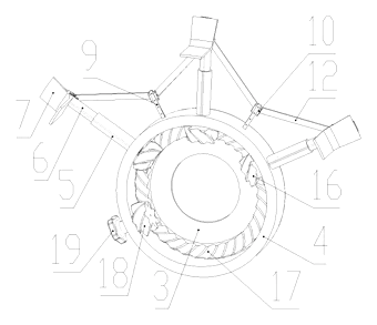
| 9 | Guide rail | Fixed on the sliding rod body and between adjacent cylinders; guides the sliding block. |
| 10 | Sliding block | Travels along the guide rail, linked to neighbors by a connecting rod. |
| 11 | Control rod | Pivots on the sliding block and connects to the upper end of the prying plate. |
| 12 | Connecting rod | Links adjacent sliding blocks so they move together. |
| 13 | Worm | Rotates in the middle of the handle; drives the central sliding block. |
| 14 | Guide rod | Fixed on the middle sliding block; its end inserts into the worm’s thread groove. |
| 15 | Output gear | Bevel gear on the drive plate, coaxial with an adjusting screw. |
| 16 | Adjusting screw | Threaded connection to the sliding rod; advances the rod when the output gear turns. |
| 17 | Input gear | Central bevel gear meshing with all output gears. |
| 18 | Adjusting gear | Meshes with the boss and the input gear. |
| 19 | Adjusting knob | Coaxial with the adjusting gear; turned by hand to set rod positions. |
| 24 | Pulley | The vehicle component from which the belt is removed. |
Operating steps
- Select the sleeve. Choose a disassembly sleeve (2) that matches the pulley’s mounting bolt and attach it to the inserting block on the disassembly handle (1).
- Anchor the tool. Fit the sleeve over the mounting bolt so the device is stably positioned on the pulley (24).
- Set the rod positions. Turn the adjusting knob (19). This rotates the adjusting gear (18), which turns the input bevel gear (17). The input gear meshes with the output bevel gears (15), spinning the adjusting screws (16) to thread the sliding rods (6) outward until the V-shaped prying plates (7) sit behind the belt edge.
- Actuate the prying mechanism. Turn the control knob on top of the worm (13). The worm rotates, engaging the thread groove with the guide rod (14) on the middle sliding block (10).
- Remove the belt. As the middle block moves, it pulls the connecting rods (12), dragging the adjacent sliding blocks along their guide rails (9). The control rods (11) pivot, pushing the upper ends of the V-shaped prying plates (7) inward while their lower tips lever the belt outward evenly around the pulley.
- Withdraw the tool. Once the belt clears the pulley flange, reverse the knobs, detach the sleeve, and pull the handle out of the engine bay.
Applications
Independent auto repair shops
Mechanics replacing serpentine or accessory belts on daily driver vehicles use this tool to avoid scraping their hands on tight engine layouts. The socket sleeve swaps quickly between jobs, fitting different bolt sizes across car brands.
Fleet maintenance garages
Technicians servicing delivery vans or transit buses need fast turnaround times. The coordinated prying action removes belts faster than manual levering, reducing the time a vehicle spends on the lift.
Automotive technical schools
Instructors teaching belt-drive systems use the device to demonstrate proper removal geometry. Students learn to apply even force around the pulley circumference instead of twisting a flat screwdriver blindly.
Roadside assistance teams
Mobile mechanics working in driveways or parking lots benefit from the compact mechanism. The perpendicular handle lets them operate the tool without leaning deeply over fenders or removing other components first.
Dealership service centers
Service bays handling warranty work require standardized procedures. This tool provides a repeatable method for belt removal that minimizes the risk of damaging adjacent sensors or wiring harnesses during the process.
Where it is less suitable
- Timing belt replacement inside sealed covers - timing belts require cover removal and precise crank/cam alignment; this tool targets externally accessible transmission and accessory pulleys.
- Heavy-duty industrial conveyors - the device is sized for automobile pulleys and mounting bolts, not large factory drive shafts.
- Belts under extreme active tension - if the tensioner cannot be relaxed first, the prying plates may not overcome the load safely.
Frequently asked questions
How does the tool actually get the belt off the pulley?
Once anchored to the pulley bolt, the sliding rods are advanced so the V-shaped prying plates sit behind the belt. Turning the control knob rotates a worm gear inside the handle. This pulls linked sliding blocks along guide rails, which pivot the control rods and force the prying plates to lever the belt outward evenly around the pulley circumference.
Does it fit every car?
The disassembly sleeve at the end of the handle is detachable. It functions as a socket spanner that fits over the pulley’s mounting bolt. You swap the sleeve for one that matches the specific bolt size of the vehicle being serviced, while keeping the same handle and prying mechanism.
Why are bevel gears used in the drive plate?
An input bevel gear meshes with multiple output bevel gears arranged around the circular boss. Each output gear is coaxial with an adjusting screw threaded into a sliding rod. Turning the adjusting knob spins the input gear, which turns all output gears simultaneously, advancing the sliding rods evenly to position the prying plates.
Can one person operate it?
Yes. The handle is positioned perpendicular to the drive plate axis. This allows the operator to stand outside the engine compartment, hold the handle steady, and turn the adjusting knob and control knob without reaching into tight spaces.
What keeps the prying plates from slipping off the belt?
The prying plates are V-shaped and pivot on the sliding rods. The geometry allows them to engage the belt edge securely as the control rods push their upper ends. The device remains anchored to the pulley’s center bolt via the socket sleeve throughout the process.
What materials are used for the gears and rods?
The patent describes the mechanical arrangement but does not specify material grades. Metal selection for the bevel gears, worm, sliding rods, and handle is set in design and confirmed on prototypes based on the torque required for the target vehicle class.
Can this design be made and sold in the US?
The patent was filed only in China and is currently in force there, meaning production or sale within China requires the owner’s permission. Because no US or other foreign counterpart was filed, this specific patent document does not restrict manufacturing or sales in the United States. However, automotive hand tools are a heavily patented field, so a freedom-to-operate check is recommended before volume production.
Are you affiliated with the patent owner?
No. IP2M is an independent design and manufacturing service working from the public patent document.
Request a quote
Click Request a Quote below to see our email address - copy it, or open your email app with a ready-made message. Please mention patent CN118636096B in the subject.
Helpful details to include:
- Your company and channel (automotive tool brand, wholesale distributor, fleet maintenance supplier, training equipment provider)
- Target vehicle types (passenger cars, light trucks, heavy-duty engines)
- Required sleeve sizes for the pulley mounting bolts
- Handle length preferences
- Material and finish specifications
- Estimated quantity and target price
- Timeline - when you would like samples and the first shipment
You can also reach us at (332) 203-9997.
Explore this product
Interested in building this?
Tell us your target market, quantity and timeline. We reply with options for prototyping, small-batch runs or volume production.
Send your inquiry to
Please put CN118636096B in the subject line and tell us your company, country, estimated quantity and timeline.
Prefer to talk? Call (332) 203-9997.
More product-ready patents
All Tools & Workshop patents →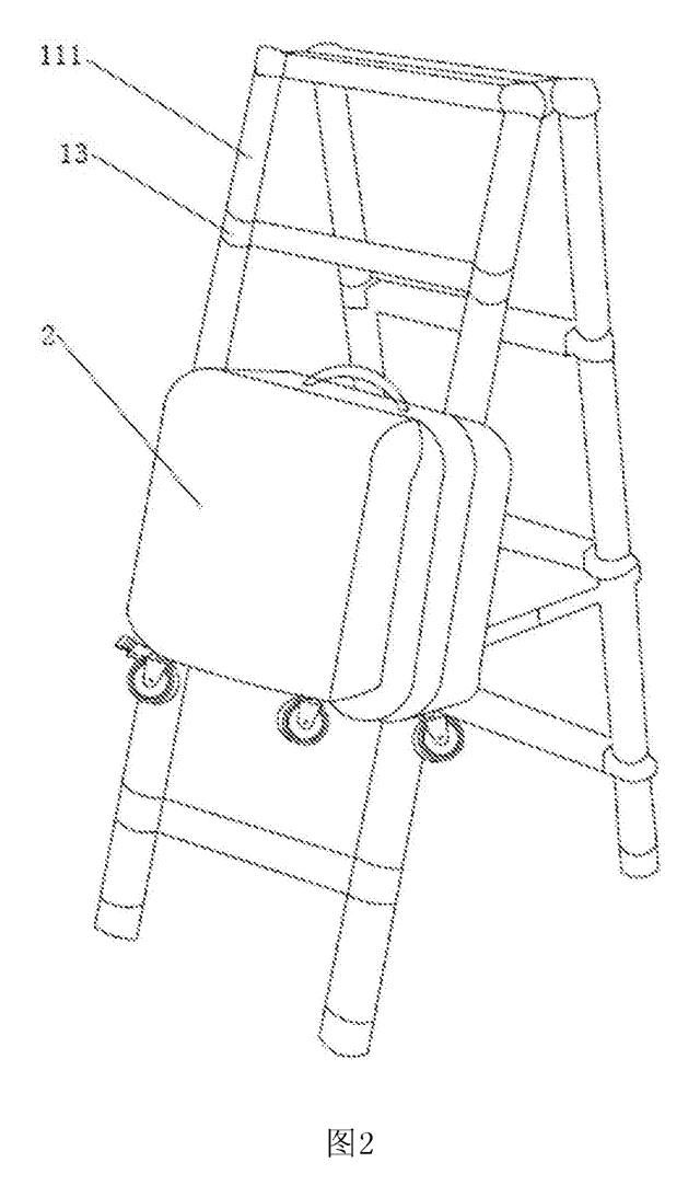
Tools & Workshop
Rolling Tool Box with Telescoping Step Ladder
Telescoping A-frame ladder with an attached rolling tool box that slides to your working height.
Patent CN206290197U
Tools & Workshop
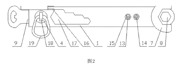
Folding 3-Handle Wrench Multi-Tool
Folding three-handle wrench multi-tool with magnetic screwdriver bits, saw, file and bottle opener.
Patent CN205290875U
Tools & Workshop
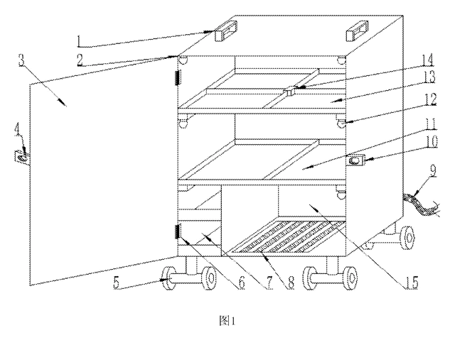
Rolling Auto-Repair Tool Cabinet with Built-In Lights
Lockable rolling tool cabinet for car repair with interior lights, a lubricant tray, parts drawers and a tool bay.
Patent CN205989314U
Tools & Workshop
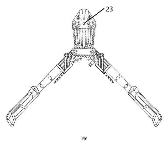
Wide-Opening Folding Bolt Cutter
Bolt cutter with linked, gear-meshing handles that open up to 190° and fold in half for storage.
Patent CN207206226U
Tools & Workshop
Nail-Holding Hammer with Fold-Out Drivers
Hammer with a nail-holding T-slot in the head and fold-out drivers stored in the handle.
Patent CN205254927U
Tools & Workshop
Modular Wrench with Screw-On Heads
Wrench handle with a three-way threaded hub for screw-on adjustable and hex heads, plus a pipe sleeve.
Patent CN206216564U
Browse by category
- Apparel & Accessories (22)
- Baby & Kids (16)
- Bags & Luggage (9)
- Bath & Personal Care (16)
- Car Accessories (10)
- Furniture, Bedding & Storage (12)
- Garden & Outdoor (18)
- Health & Wellness (8)
- Home, Kitchen & Cleaning (24)
- Lighting (12)
- Packaging & Containers (6)
- Pet Products (6)
- Phone & Camera Accessories (4)
- Retail Display (13)
- School, Office & Art (19)
- Sports & Recreation (25)
- Tools & Workshop (27)
- Toys & Games (12)
This page is based on the public patent document CN118636096B, assigned to Weifang Hetong Motor Vehicle Testing Co ltd. IP2M is an independent manufacturing service and is not affiliated with, endorsed by or licensed by the patent owner. Images marked as concept renderings are illustrations, not photos of an existing product. Patent status information is provided for reference only and is not legal advice; confirm freedom to operate for your market before production. Full disclaimer.