At a glance
| Patent number | CN118636096B (application CN202411124741) |
| Type | China invention patent (发明专利) - protects product shape, structure and method |
| Original title | Automobile transmission belt dismounting device (一种汽车传动皮带拆卸装置) |
| Patent owner | Weifang Hetong Motor Vehicle Testing Co ltd |
| Inventors | Dai Jun, Wu Haihua, Fan Rong, Jia Chunnan, Chi Mengjuan, Bao Chunbao, Lu Shuaishuai, Chen Li, Liu Wei, Li Wei |
| Filing date | 2024-08-16 |
| Grant date | 2024-11-29 |
| Status (China) | In force in China until at most 2044-08-16 (if annual fees are paid) |
| Patent family | Chinese filings only - no US, European, Japanese, PCT or other filings listed |
| Cited by | 1 later document |
| Source | Google Patents (search for CN118636096B) |
What the claims cover, in plain language
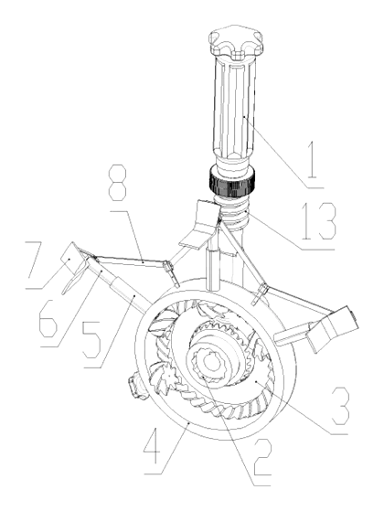
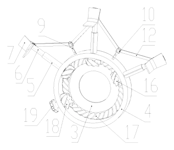
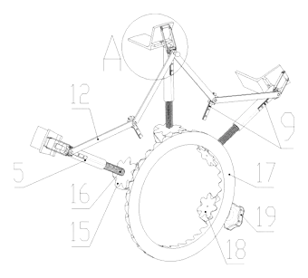
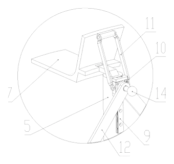
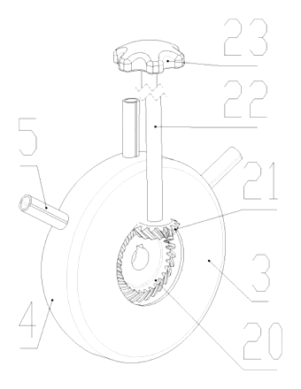
Claim 1 - an automobile transmission belt disassembly device comprising a disassembly handle (1) detachably connected to a pulley (24). A disassembly sleeve (2) is detachably arranged at one end of the handle and connects to the pulley’s mounting bolt. A drive plate (3) rotates on the handle near the sleeve. A circular boss (4) is fixed on the drive plate, carrying multiple fixed cylinders (5). A sliding rod (6) slides inside each cylinder, and a prying plate (7) for prying the belt rotates on the rod’s outer end. A prying mechanism (8) drives the prying plates. The prying mechanism includes a guide rail (9) on the sliding rod, a sliding block (10) on the rail, and a control rod (11) rotating on the block and connected to the prying plate’s upper end. Between adjacent cylinders, guide rails fixed to the boss carry sliding blocks linked by connecting rods (12). A worm (13) rotates in the handle’s middle with a control knob on top. A guide rod (14) on the middle sliding block inserts into the worm’s thread groove when the middle sliding rod is flush with the handle.
Claim 2 - the prying plate (7) is V-shaped, and its middle part is rotatably connected to the sliding rod (6).
Claim 3 - the drive plate (3) carries multiple rotatable output gears (15), each with a coaxial adjusting screw (16) threaded to a sliding rod (6). An input gear (17) on the drive plate meshes with the output gears. The input and output gears are bevel gears.
Claim 4 - an adjusting gear (18) meshes with the boss (4) and the input gear (17), and has a coaxial adjusting knob (19).
This is a simplified reading for orientation only. The legal scope is defined by the exact claim wording in the official Chinese document.
What this means for US production
This patent was filed only in China and is currently in force; making or selling the described device in China needs the owner’s permission. It has no US or other foreign counterpart.
Two points to settle early:
- Other patents may exist. Automotive hand tools and belt service equipment are actively patented fields. While no foreign patents citing this specific document were identified, other manufacturers hold US patents covering belt tensioners, pulley holders, and pry tools. A freedom-to-operate (FTO) review of the worm-driven linkage and socket-anchored prying concept is needed before tooling.
- Torque capacity. The strength of the adjusting screws, bevel gears, and prying plates must be matched to the belt tension forces encountered in target vehicle classes; material grades and heat treatment are set in design and confirmed on prototypes.
Customization and manufacturing
What can be customized
| Area | Options |
|---|---|
| Sleeve sizes | Interchangeable socket spans to fit various pulley bolt diameters |
| Handle length | Extended or shortened handles depending on engine bay depth requirements |
| Number of cylinders | Three or more fixed cylinders and prying plates to match pulley diameters |
| Materials | Carbon steel, alloy steel, or stainless steel for the handle, rods, and plates |
| Surface finish | Black oxide, zinc plating, or powder coating for corrosion resistance |
| Knob design | Shape and grip texture of the control knob and adjusting knob |
Things to plan for (US market)
- ASME B107 - hand tool standards covering socket attachments and drive fittings used in the disassembly sleeve interface.
- California Prop 65 - surface treatments, plating chemicals, and polymer grips must be screened for listed substances.
- OSHA general duty - professional shop tools sold in the US should include clear instruction manuals detailing safe operating torque limits and pinch points.
How a project runs
- Inquiry - define target vehicle classes, required sleeve sizes, handle lengths, and quantities.
- Design - engineer the bevel gear ratios, worm pitch, sliding rod stroke, and prying plate geometry.
- Prototype - machine samples to test gear meshing, worm engagement, and prying force distribution on actual pulleys.
- Pilot run - produce a small batch for fatigue testing on the adjusting screws and connecting rods under repeated belt-tension loads.
- Production - forge or machine the handle, stamp the drive plate and boss, cut and hob the bevel gears and worm, assemble, and apply finishes.
Quantities & timeline
The handle and drive plate require forging dies or precision CNC machining setups. The bevel gears, worm, and adjusting screws need hobbing and threading tooling. The fixed cylinders and sliding rods are machined or drawn components. Assembly involves pressing the gears onto the drive plate and fitting the prying mechanism linkages. Certification tests for socket fitment and material hardness add to the schedule. Send us your target vehicle applications, required sleeve sizes, handle length, material preferences, quantity and target price and we will reply with options.
Patent drawings
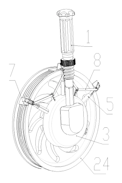
Drawings reproduced from the public patent document for reference.