
Patent CN118816056B
Updated November 4, 2026Laser Level with Adjustable Vertical Rod Bracket and Height/Tilt Control
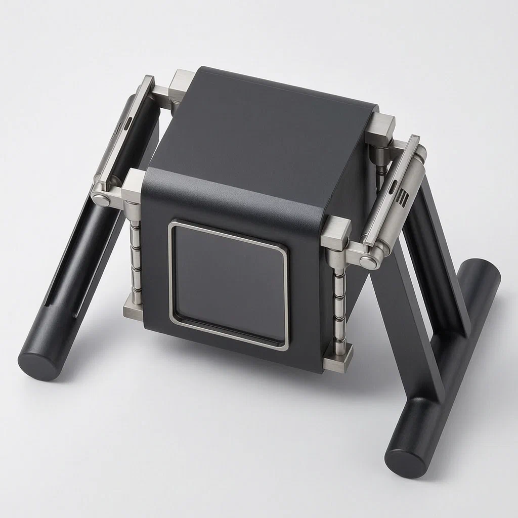
Standard laser levels sit flat or hang from a tripod, making angled projections difficult. Adjusting height usually requires loosening clamps or moving the entire unit up and down on a stand. This design integrates a compact bracket directly onto the laser body. It uses four vertical rods with spring-loaded snap-fit seats for rapid height changes. For angle control, rotating brackets lock into place using a magnetic slider that engages with pre-set arc grooves. This allows users to set precise tilts on one or both sides quickly, enabling diagonal line projection without external accessories.
- China invention patent - active
- No filings outside China
- Construction tool accessory
- Vertical rod slides, magnetic tilt locks
Splat! What let you down?
📏
Tool-free height adjust
Spring-loaded blocking blocks snap into grooves on vertical rods, allowing quick slide positioning.
🔄
Magnetic tilt lock
Arc-shaped grooves and a magnet-based limit block secure the bracket at fixed angles.
⚖️
Dual-side control
Adjust left and right brackets independently to create slopes or simultaneously for height changes.
🔩
Integrated structure
Brackets mount directly to the laser body via upper and lower fixing blocks, no separate stand needed.
Bring this product to market
- ✓ Patent review Patent family and legal status reviewed in the relevant jurisdictions.
- 2 Product brief · now How it works, uses and options written up
- 3 Prototype First samples for buyers to review
- 4 Pilot run Small first batch for launch customers
- 5 Volume production Repeat orders at scale
Buyer interest
– of 100 buyers needed to start prototyping
One click, no sign-up. Each vote is one real visitor, and products with the most interest go to prototyping first.
Build team: no members yet. Need a partner, co-funding or skills to build this? Join and we introduce the team once it forms.
Patent Rights & Team Participation
Before joining a development team, participants should ensure they have the necessary rights or authorization to participate in the project.
Participation is generally appropriate where:
- You own the relevant patent rights or have obtained permission or a license from the rights holder.
- The relevant patent rights have expired or have been legally invalidated in the jurisdictions where the planned activities will take place.
- The planned development, manufacturing, and commercialization activities have been independently assessed and do not infringe applicable patent rights in the relevant jurisdictions.
Important: Being located outside a country where a patent is protected does not automatically exempt you from patent infringement risks. Patent rights may apply based on where development, manufacturing, use, sale, or import activities take place.
IP2M does not grant any patent license or authorization through team participation. Joining a project does not provide permission to use, manufacture, or commercialize patented technology.
The problem
Traditional laser levels often rely on external tripods or simple clamps for height and angle adjustments. Changing the height typically involves loosening a knob, sliding the unit up a pole, and retightening, which is slow and imprecise. Setting a specific tilt angle is even harder; users must guess the angle or use additional mounting arms that can shift during operation. When working on stairs, ramps, or sloped ceilings, maintaining a consistent diagonal line requires a stable, repeatable angle setting that standard flat-mount devices cannot provide without complex rigging.
The solution
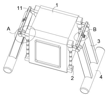
The patent describes a laser level body (1) equipped with an internal adjustable bracket system.
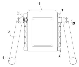
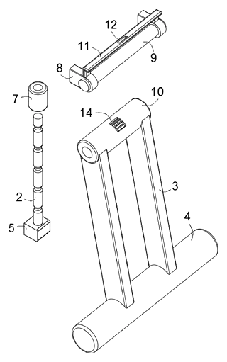
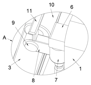
- Four vertical rods (2) are symmetrically mounted on both sides of the body, held by upper (6) and lower (5) fixing blocks.
- Sliding seats (7) fit over these rods. Inside each seat, blocking blocks (18) are pushed inward by compression springs (20). These blocks engage with adapting grooves (16) spaced along the rods, locking the seat’s height. Pulling the bracket down compresses the springs, releasing the lock for adjustment.
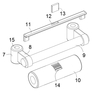
- Each sliding seat connects to a fixing plate (8) and an adjustment bracket body (3).
- The bracket body rotates around a rotating shaft (9) attached to an adjustment sleeve (10).
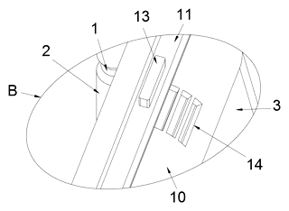
- The sleeve features multiple limiting grooves (14) arranged in an arc. A limit block (13), described as a magnet piece, slides in an auxiliary groove (12) on a limit frame (11) atop the fixing plate.
- To set an angle, the user pulls the limit block out, rotates the bracket, and pushes the block back into the desired groove. The magnetic attraction holds the block securely in the iron-sheet groove, fixing the tilt.
Who it is for
- Construction contractors needing fast height and angle changes for framing and flooring without frequent tripod repositioning.
- Home improvement DIYers who want simpler adjustments than traditional clamp-and-pole systems offer.
- Tile and flooring installers requiring precise diagonal lines for pattern layouts on uneven surfaces.
- Equipment manufacturers looking to differentiate their laser levels with integrated, tool-free adjustment mechanisms.
How it works
The main parts
| No. | Part | What it does |
|---|---|---|
| 1 | Laser level body | Houses the optics and electronics. |
| 2 | Adjustment vertical rods | Guide rails for height movement; contain adapting grooves (16). |
| 5, 6 | Lower/Upper fixing blocks | Secure the rods to the body. |
| 7 | Sliding seat | Moves up/down the rods; contains spring-loaded locks. |
| 18, 20 | Blocking block & Spring | Snap-fit mechanism that locks the seat at specific heights. |
| 3 | Adjustment bracket body | Rotates to change tilt angle; supports the laser. |
| 9, 10 | Shaft & Adjustment sleeve | Pivot point for rotation; sleeve has arc-shaped limiting grooves (14). |
| 11, 13 | Limit frame & Block | Holds the magnetic slider that locks the angle. |
Operating steps
- Height Adjustment: Grasp the adjustment bracket body (3) and pull downward. This action, transmitted through the sleeve (10), forces the sliding seat (7) down against the spring tension. The blocking blocks (18) retract from the current adapting groove (16). Slide the seat to the new position and release; the springs push the blocks into the next groove, locking the height.
- Tilt Adjustment: Pull the limit block (13) outward from its groove. Rotate the bracket body (3) around the shaft (9). Align the block with a different limiting groove (14) on the sleeve. Push the block in; the magnet snaps it into the iron sheet groove, securing the angle.
- Slope Creation: Adjust one side’s bracket to a different angle than the other to tilt the laser plane diagonally.
Applications
Staircase Layouts
Contractors can tilt the laser to match the slope of a staircase stringer. By adjusting one side higher than the other, the projected line follows the incline, helping mark tread positions accurately without calculating offsets.
Sloped Ceiling Work
For vaulted or cathedral ceilings, the dual-side tilt allows the laser plane to align with the roof pitch. Installers can set the exact angle once and move the unit along the wall, maintaining a consistent reference line for drywall or trim.
Flooring Diagonals
Tile setters often lay patterns at 45-degree angles. The arc-groove locking system provides discrete, repeatable angle settings. Users can lock the bracket at a diagonal orientation to project grid lines across the floor surface.
Rapid Height Changes
In open-construction sites where the floor level varies or obstacles appear, workers can slide the laser up or down the vertical rods in seconds. The spring-loaded snap-fit eliminates the need to loosen knobs, speeding up setup time between rooms.
Where it is less suitable
- Long-range outdoor surveying: Tripod-mounted lasers with fine-adjustment screws offer better stability and precision for kilometers-long lines.
- Extreme vibration environments: While the magnetic lock is secure, heavy machinery vibrations might cause gradual drift if the groove engagement is not tight enough.
- Simple horizontal leveling: If no tilt or height change is needed, a basic self-leveling laser is cheaper and lighter.
Patent & Production
At a glance
| Patent number | CN118816056B (application CN202411315295) |
| Type | China invention patent (发明专利) - protects product shape, structure, and method |
| Original title | Laser level with adjustable bracket (具有可调节支架的激光水平仪) |
| Patent owner | Nantong Siwoqi Electronic Technology Co ltd |
| Inventors | Mao Yanfeng |
| Filing date | 2024-09-20 |
| Grant date | 2024-12-06 |
| Status (China) | In force - valid until at most 2044-09-20, provided annual fees are paid |
| Patent family | Public record shows Chinese filings only - no US, European, Japanese, PCT or other filings listed |
| Cited by | 0 later documents |
| Source | Google Patents (search for CN118816056B) |
What the claims cover, in plain language
Claim 1 defines a laser level with an adjustable bracket comprising a body (1), four vertical rods (2), and a bracket system. Key elements include: sliding seats (7) on the rods; fixing plates (8); limit frames (11) with auxiliary grooves (12); a tilt adjustment component with a rotating shaft (9) and adjustment sleeve (10); and a height adjustment component with adapting grooves (16) and spring-loaded blocking blocks (18). The blocking blocks snap into the grooves to lock height. The adjustment sleeve has multiple arc-shaped limiting grooves (14) that engage with a limit block (13) to lock the tilt angle.
Claim 2 specifies that the sliding seat has a vertical sliding groove (15) and the rod has evenly distributed adapting grooves (16), with at least four grooves. Claim 3 details the first groove (17) inside the seat that houses the blocking block. Claim 4 adds a buffer plate (19) behind the blocking block within the groove. Claim 5 specifies compression springs (20) connecting the blocking block and buffer plate. Claim 6 notes that the contact surfaces of the grooves and blocks are arc-shaped for smooth engagement. Claim 7 sets dimensional relationships: the support bottom rod diameter is larger than the sleeve, and its length exceeds the body length.
This is a simplified reading for orientation only. The legal scope is defined by the exact claim wording in the official Chinese document.
What this means for US production
This patent was filed in China and is currently in force. Making or selling this specific configuration in China would require the owner’s permission. However, the public record shows no US counterpart or foreign family members. Therefore, the patent itself does not restrict manufacturing or sales in the United States based solely on this document.
Two points to settle early:
- Other patents may exist. Laser level mounting and adjustment mechanisms are a competitive field with many existing utility patents in the US covering various tripod adapters, magnetic mounts, and leveling systems. A freedom-to-operate (FTO) review is recommended to ensure the spring-loaded snap-fit height adjustment and magnetic arc-groove tilt lock do not infringe on broader existing US patents in this category.
- Component sourcing. The design relies on specific spring rates and magnet grades to function correctly. Sourcing consistent components is critical for the snap-fit reliability described in the claims.
Customization and manufacturing
What can be customized
| Area | Options |
|---|---|
| Rod Material | Aluminum extrusion or steel tube for rigidity |
| Seat Housing | PC or ABS injection molding for impact resistance |
| Spring Type | Compression coil springs with varying rates for tactile feedback |
| Locking Mechanism | Magnet grade (e.g., N52) for stronger retention; groove count for finer angle steps |
| Finish | Anodizing for rods; rubberized coating for seats |
| Mounting Interface | Standard 1/4-20 thread compatibility for tripod adapters |
Things to plan for (US market)
- OSHA / ANSI Safety Standards: Ensure the device does not obscure laser safety labels and meets Class II laser emission limits if the housing is modified.
- RoHS Compliance: If sold in California or other states with strict hazardous substance laws, verify solder and plasticizers in molded parts.
- Drop Testing: Construction tools face rough handling; validate the snap-fit durability under repeated shock.
How a project runs
- Inquiry - Confirm rod lengths, number of height steps, and angle increments.
- Design - Mold flow analysis for the sliding seat; select spring constants.
- Prototype - CNC machined rods; 3D printed seats for fit testing.
- Pilot run - Assembly with real magnets and springs; cycle testing.
- Production - Injection molding, aluminum machining, magnet assembly.
Quantities & timeline
Tooling costs depend on the complexity of the sliding seat mold, which includes internal cavities for the spring and blocking block. CNC machining time for the vertical rods scales with quantity. Magnet assembly requires careful alignment to avoid interference. Send us your target retail price, annual volume, and specific adjustment requirements and we will reply with options.
Production notes
Tooling and process
Injection molds are required for the sliding seats and limit frames, likely using PC or ABS materials. The vertical rods typically involve aluminum CNC machining or extrusion followed by cutting. Magnet assembly is a manual or semi-automated step where the limit block is inserted into the auxiliary groove.
Cost drivers
Mold count typically drives upfront costs, particularly for the multi-cavity seats. CNC time for the rods is usually significant if high tolerances are needed for the adapting grooves. Magnet grade affects material cost, with stronger neodymium magnets increasing expenses. Packaging must protect the delicate snap-fit mechanisms during shipping.
Prototyping path
Prototyping usually starts with a 3D-printed fit sample to test the blocking block engagement with the adapting grooves. Use CNC housings for initial functional prototypes. Perform magnet pull tests to determine the correct grade for the limit block. Check for RF interference if the laser module has wireless connectivity. Proceed to tooling after validating the spring rate consistency.
What we would change before tooling
We would likely verify the arc-shaped contact surfaces of the blocking blocks and grooves first to ensure smooth sliding without binding. Test the buffer plate thickness to prevent spring fatigue over thousands of cycles. Confirm that the magnetic strength holds the angle firmly under vibration but allows easy manual release.
Common failure points
Spring fatigue can lead to inconsistent locking force. Magnet strength loss over time or due to heat could cause angle drift. Adhesive failure is unlikely if mechanical retention is used, but poor joint design in the molded seat could cause cracking. Drop protection must be sufficient to keep the sliding seat aligned after impacts.
Patent drawings
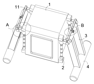
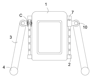
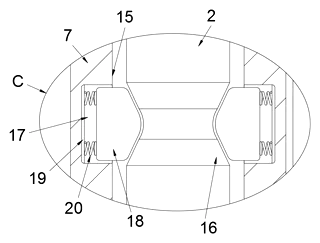
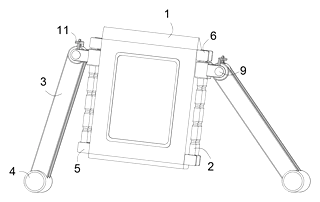
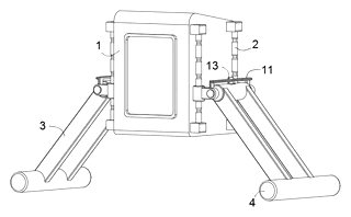
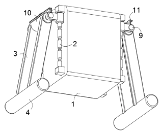
Drawings reproduced from the public patent document for reference.
Frequently asked questions
How does the height adjustment work?
It uses a spring-loaded snap-fit system. Blocking blocks inside the sliding seat are pressed into grooves on the vertical rods by compression springs. To change height, you pull the bracket down, which retracts the blocks, allowing the seat to slide. Releasing it lets the springs push the blocks into the next groove, locking it instantly without tools.
Is the tilt adjustment precise?
The tilt is controlled by a magnetic limit block that slides into arc-shaped grooves on the adjustment sleeve. This provides fixed angle stops rather than continuous infinite adjustment. The number of grooves determines the granularity of the angle settings, which can be customized in design.
Can I adjust the sides independently?
Yes. Each side has its own bracket and locking mechanism. You can tilt one side while keeping the other horizontal, or tilt both to different degrees, allowing the laser plane to be angled diagonally for tasks like stairs or sloped floors.
Will the magnets lose strength over time?
Neodymium magnets generally retain their strength well unless exposed to extreme heat or corrosion. The patent suggests using iron sheets for the grooves to enhance the magnetic hold. Proper plating and encapsulation in the molded parts help protect against environmental factors.
Is it compatible with standard tripods?
The laser body typically retains its standard mounting interface (like 1/4-20 thread). The bracket system is integrated into the device itself, so you don’t need a special tripod adapter for the height/tilt functions, though you can still mount the whole unit on a tripod if desired.
How durable is the snap-fit mechanism?
The blocking blocks and grooves are designed for repeated engagement. Durability depends on the material hardness of the molded seat and the spring rate. In most designs, these parts are made from engineering plastics like PC or ABS to withstand wear.
Can this design be made and sold in the US?
The patent is filed in China and is in force there. The public record shows no US counterpart, so this specific patent does not restrict making or selling the design in the US. However, other US patents may cover similar adjustment mechanisms, so a freedom-to-operate check is recommended before volume production.
Are you affiliated with the patent owner?
No. IP2M is an independent design and manufacturing service working from the public patent document.
Request a quote
Click Request a Quote below to see our email address - copy it, or open your email app with a ready-made message. Please mention patent CN118816056B in the subject.
Helpful details to include:
- Your company and channel (tool brand, construction supplier, hardware retailer)
- Adjustment specs (number of height steps, angle increments)
- Material preferences (rod type, plastic grade)
- Estimated quantity and target price
- Timeline - when you would like samples and the first shipment
You can also reach us at (332) 203-9997.
Page editor: Emily Zhang, Product Editor · IP2M
Last updated November 4, 2026. If something on this page looks wrong, email [email protected] and we will check it against the patent.
Interested in building this?
Tell us your target market, quantity and timeline. We reply with options for prototyping, small-batch runs or volume production.
Send your inquiry to
Please put CN118816056B in the subject line and tell us your company, country, estimated quantity and timeline.
Prefer to talk? Call (332) 203-9997.
More product-ready patents
All Phone & Camera Accessories patents →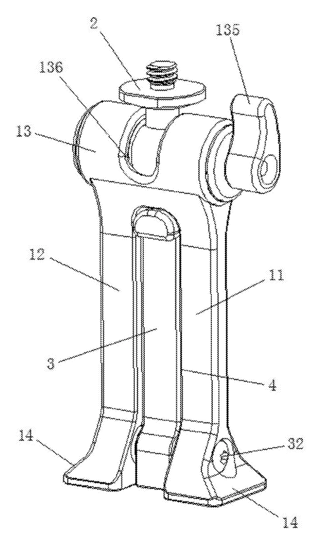
Phone & Camera Accessories
Phone Clip Mount with Fold-Out Stand Leg
Phone clamp adapter with a ball-joint top, a dovetail base for tripod clamps and a fold-out desk leg.
Patent CN207394276U
Stands & Mounts
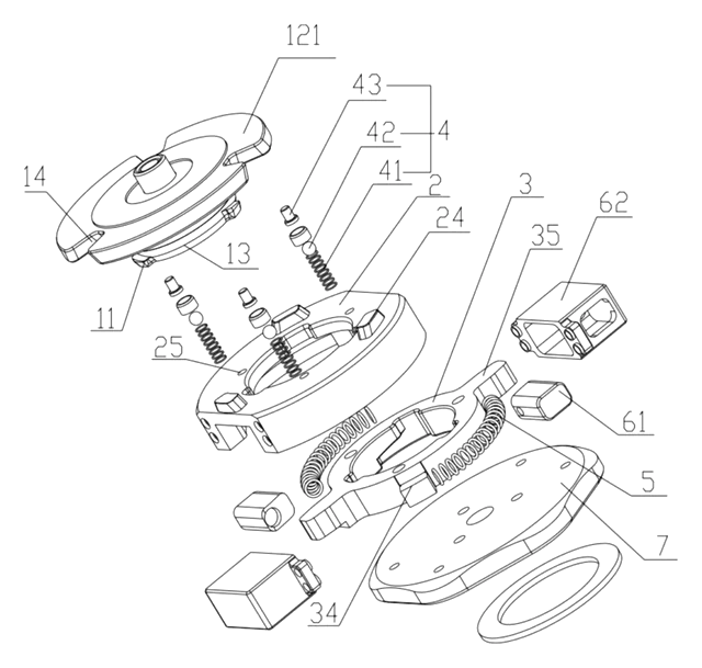
Manual Quick-Release Connector for Camera Equipment
Quick-release camera mount using a rotating driver and spring-loaded locking grooves.
Patent CN215294199U
Phone & Camera Accessories
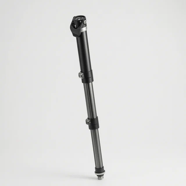
Extendable Support Leg and Monopod with Single-Knob Locking
Three-section monopod leg locked and released from one top knob via a transmission rod.
Patent CN113090903B
Phone & Camera Accessories
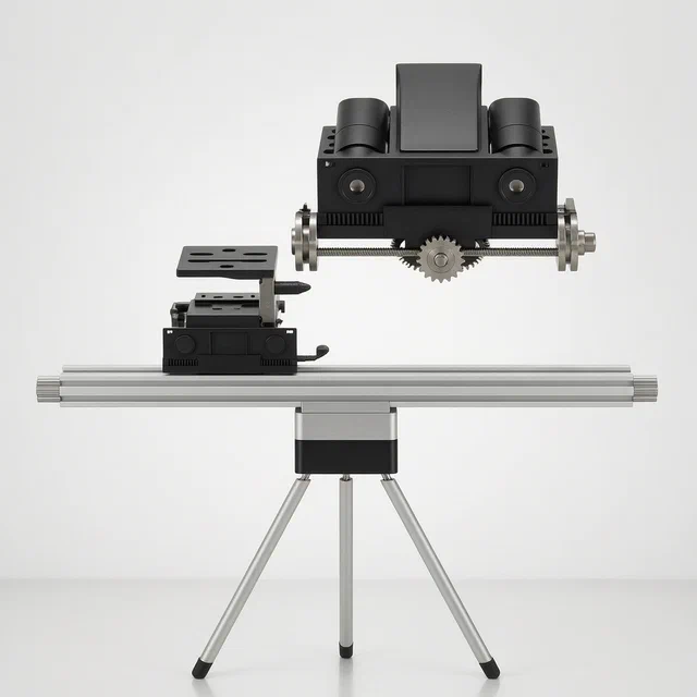
Remote-Controlled Outdoor Photography Tripod with Movable Lens Mount
Motorized tripod with a remote-driven camera seat and a sliding multi-lens mount.
Patent CN118328254B
Phone & Camera Accessories
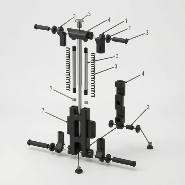
Foldable Multifunctional Mobile Phone Clip with Rotating Support Feet
Foldable phone clip with rotating tripod-compatible feet and 1/4-inch screw mounts.
Patent CN207112268U
Phone & Camera Accessories
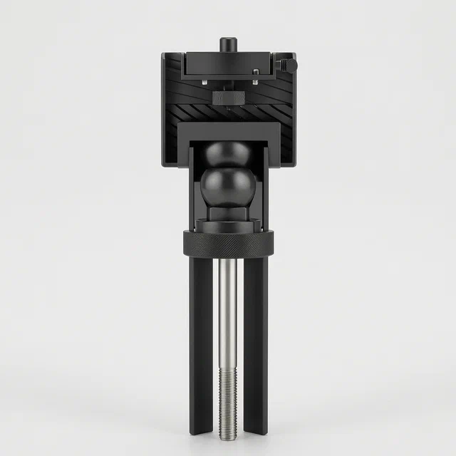
One-Touch Locking Ball Head Mount for Cameras and Equipment
Single-knob ball head mount that locks the ball and secures the device in one rotation.
Patent CN220930728U
Browse by category
- Apparel & Accessories (38)
- Baby & Kids (26)
- Bags & Luggage (15)
- Bath & Personal Care (26)
- Car Accessories (21)
- Furniture, Bedding & Storage (20)
- Garden & Outdoor (28)
- Health & Wellness (12)
- Home, Kitchen & Cleaning (43)
- Lighting (20)
- Packaging & Containers (10)
- Pet Products (9)
- Phone & Camera Accessories (8)
- Retail Display (21)
- School, Office & Art (30)
- Sports & Recreation (37)
- Tools & Workshop (46)
- Toys & Games (19)
This page is based on the public patent document CN118816056B, assigned to Nantong Siwoqi Electronic Technology Co ltd. IP2M is an independent manufacturing service and is not affiliated with, endorsed by or licensed by the patent owner. Images marked as concept renderings are illustrations, not photos of an existing product. Patent status information is provided for reference only and is not legal advice; confirm freedom to operate for your market before production. Full disclaimer.