
Patent CN118902352B
Updated November 6, 2026Dish Rack with Cam-Locked Sliding Partitions and Removable Drain Tray
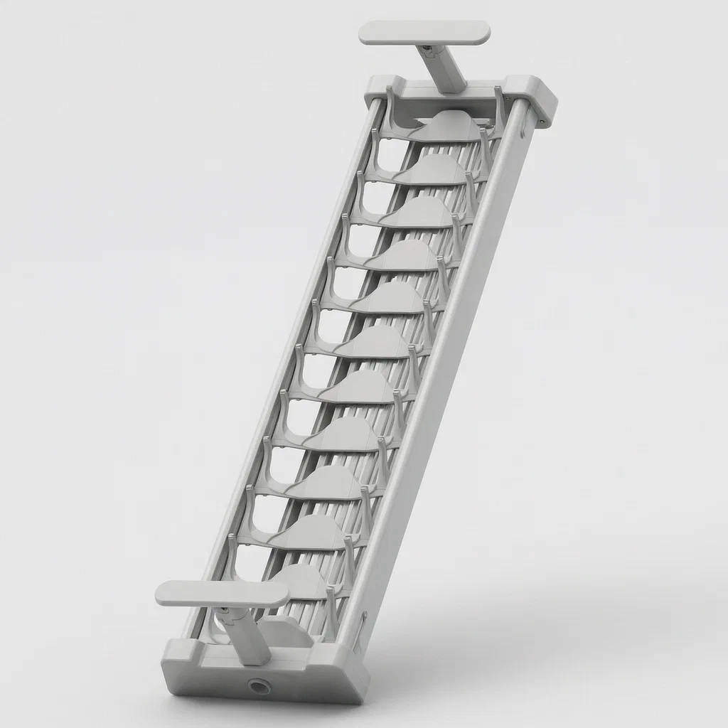
Standard dish racks often have fixed dividers that cannot accommodate large platters or awkwardly shaped items. This design introduces a sliding partition system controlled by an eccentric cam connector. By rotating the connector, a guide post moves within a slot while a limit protrusion engages or disengages from a groove, locking the divider in place without complex fasteners. The rack also features a modular drain tray that snaps into the base using a spring-loaded locking pin, making it simple to remove for washing. This configuration offers flexible storage capacity and streamlined maintenance for busy kitchens.
- China invention patent - active
- No filings outside China
- Kitchen organization hardware
- Eccentric cam locking, snap-fit drain tray
Splat! What let you down?
🔄
Eccentric Cam Lock
Rotating the connector shifts the slider and engages the lock simultaneously.
📏
Adjustable Spacing
Sliding partitions allow custom spacing for plates, bowls, or cutting boards.
💧
Removable Drain
Spring-loaded pin secures the drain tray; pull to release for cleaning.
🛠️
Tool-Free Assembly
Snap-fit and cam-lock mechanisms require no screws or tools for setup.
Bring this product to market
- ✓ Patent review Patent family and legal status reviewed in the relevant jurisdictions.
- 2 Product brief · now How it works, uses and options written up
- 3 Prototype First samples for buyers to review
- 4 Pilot run Small first batch for launch customers
- 5 Volume production Repeat orders at scale
Buyer interest
– of 100 buyers needed to start prototyping
One click, no sign-up. Each vote is one real visitor, and products with the most interest go to prototyping first.
Build team: no members yet. Need a partner, co-funding or skills to build this? Join and we introduce the team once it forms.
Patent Rights & Team Participation
Before joining a development team, participants should ensure they have the necessary rights or authorization to participate in the project.
Participation is generally appropriate where:
- You own the relevant patent rights or have obtained permission or a license from the rights holder.
- The relevant patent rights have expired or have been legally invalidated in the jurisdictions where the planned activities will take place.
- The planned development, manufacturing, and commercialization activities have been independently assessed and do not infringe applicable patent rights in the relevant jurisdictions.
Important: Being located outside a country where a patent is protected does not automatically exempt you from patent infringement risks. Patent rights may apply based on where development, manufacturing, use, sale, or import activities take place.
IP2M does not grant any patent license or authorization through team participation. Joining a project does not provide permission to use, manufacture, or commercialize patented technology.
The problem
Traditional dish racks often feature rigid, fixed dividers that limit flexibility. Users struggle to fit oversized items like serving platters, cutting boards, or irregularly shaped bowls because the spacing between slots is permanent. Furthermore, many racks rely on complex screw-based adjustments that loosen over time due to vibration and moisture exposure, requiring frequent retightening. Cleaning is another significant hurdle; standing water accumulates in fixed trays that are difficult to detach, leading to mold growth and unpleasant odors. The challenge is to create a storage system that allows users to dynamically adjust internal spacing with a simple motion while ensuring the drainage component can be removed instantly for thorough hygiene without compromising structural stability during use.
The solution
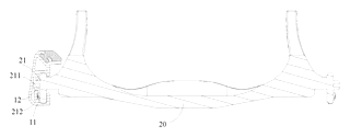
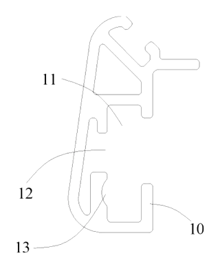
The patent describes a dish rack comprising a support frame and partition pieces connected by specialized connectors. The core innovation lies in the eccentric cam mechanism used to lock the sliding partitions. The support frame contains a sliding slot with a guide slot on its side wall. The partition’s connecting piece features a guide post that enters this slot. When the user applies force to rotate the connector, the eccentric arrangement causes the guide post to move along the guide slot while simultaneously engaging or disengaging a limit protrusion with a corresponding limit groove on the frame. This single rotational action both positions the divider and locks it firmly in place. Additionally, the rack includes a drain member positioned at the bottom of the stacking space. It utilizes a first locking member with an elastic element that urges it into engagement with a second locking member on the drain tray, allowing for quick snap-in installation and easy removal.
Who it is for
- Kitchenware Brands looking to differentiate their drying racks with adjustable, tool-free mechanisms that appeal to consumers seeking versatility.
- Small Apartment Dwellers who need to maximize limited counter space by configuring the rack to hold specific daily dishes rather than generic uniform slots.
- Hospitality Suppliers providing equipment for cafes or restaurants where rapid reconfiguration for different meal services (breakfast vs. dinner ware) is necessary.
- DIY Enthusiasts interested in modular home organization solutions that do not require drilling or permanent fixtures.
How it works
The main parts
| No. | Part | What it does |
|---|---|---|
| 10 | Support Frame | Main structure with sliding slots and limit grooves. |
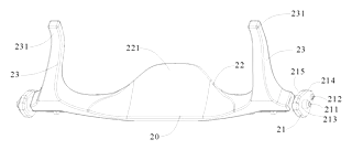
| 20 | Partition Piece | Divider for plates/bowls; connects via the connector. |
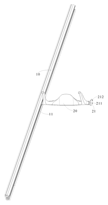
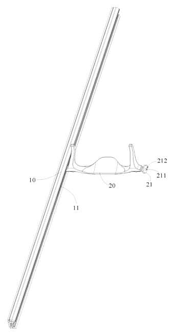
| 21 | Connecting Piece | Eccentric cam structure linking partition to frame. |
| 21a | Guide Post | Second sliding part that moves in the guide slot. |
| 21b | Limit Protrusion | Second limiting part that engages/disengages the groove. |
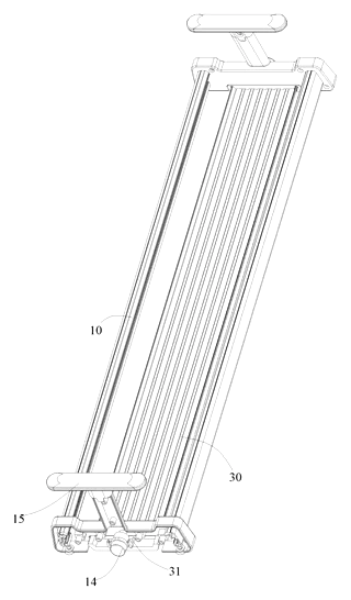
| 30 | Drain Member | Collects water; includes connecting seats and plate. |
| 14 | First Locking Member | Spring-loaded pin on the frame for the drain. |
| 31 | Second Locking Member | Socket/receptacle on the drain seat. |
Operating Steps
- Unlock: Rotate the connecting piece (21). The eccentric motion withdraws the limit protrusion (21b) from the limit groove, freeing the partition.
- Slide: Move the partition piece (20) along the sliding slot. The guide post (21a) travels within the guide slot, maintaining alignment.
- Lock: Rotate the connecting piece back. The limit protrusion drops into the new position’s limit groove, securing the divider against lateral movement.
- Install Drain: Align the drain member (30) with the frame bottom. Push until the spring-loaded first locking member (14) snaps into the second locking member (31), fixing the tray in place.
- Remove Drain: Pull the locking member away from the frame against the spring force to disengage, then lift the drain tray out for cleaning.
Applications
Plate Storage Configuration
Users can widen the gap between two partitions to accommodate large dinner plates or narrow it for saucers. The cam lock ensures the dividers stay put even when heavy ceramic plates are inserted or removed, preventing the rack from collapsing under uneven weight distribution.
Cutting Board and Lid Organization
Vertical items like cutting boards or pot lids often fall out of standard racks. By adjusting the partitions to create a wide, stable channel, these flat items can be stored upright. The locking mechanism provides the rigidity needed to keep tall, thin objects vertical without tipping.
Rapid Cleaning Routine
After washing, the entire drain tray can be popped out with one hand. This allows users to rinse the tray separately and wipe down the frame’s interior surfaces, which are usually inaccessible in fixed-tray models. This reduces the buildup of food residue and bacteria in hidden crevices.
Compact Kitchen Countertops
For kitchens with limited counter depth, the ability to push partitions together creates a smaller footprint when not in full use. Conversely, spreading them out maximizes capacity when hosting. The tool-free adjustment means the configuration can change daily based on the volume of dishes generated.
Where it is less suitable
- Heavy Industrial Use - Plastic components may degrade under extreme heat or heavy chemical cleaning agents common in commercial laundries.
- Fixed-Layout Cabinets - If the rack must fit into a pre-existing niche with exact dimensions, the sliding mechanism adds complexity compared to static wire racks.
- High-Vibration Environments - While the cam lock is secure, continuous heavy vibration might eventually wear the plastic interface points faster than metal-on-metal systems.
Patent & Production
At a glance
| Patent number | CN118902352B (application CN202411414640) |
| Type | China invention patent - protects product shape, structure, and method |
| Original title | Dish Rack (一种碗碟架) |
| Patent owner | Guangdong Tute Precision Hardware Technology Co ltd |
| Inventors | Wang Zhengyu, Wu Sitao, Jiang Chenghao |
| Filing date | 2024-10-10 |
| Grant date | 2025-02-11 |
| Status (China) | In force - valid until at most 2044-10-10, subject to payment of annual fees |
| Patent family | Public record shows Chinese filings only - no US, European, Japanese, PCT or other filings listed |
| Cited by | 0 later documents |
| Source | Google Patents (search for CN118902352B) |
What the claims cover, in plain language
Claim 1 defines a dish rack with a support frame and partition pieces. The key feature is a connecting piece with a second sliding part and a second limiting part that are eccentrically arranged. Rotating the connecting piece around the sliding part as a center moves the limiting part up or down to engage or separate from a first limiting part on the frame, thereby locking or unlocking the slide.
Claims 2-4 specify the mechanical details: the frame has a sliding slot with a guide slot (first sliding part) and a limit groove (first limiting part). The connector has a guide post (second sliding part) and a limit protrusion (second limiting part). The limit groove is arcuate, and the protrusion has a guide surface for smooth engagement during rotation.
Claims 5-7 describe locking surfaces on the connector that engage the channel walls after locking or unlocking, and define the connector as a cam structure.
Claims 8-9 detail the partition itself, which has a chassis, support sheet, and arms with arcuate surfaces to cradle dishes.
Claim 10 covers the drain member, which attaches to the frame via a first locking member (spring-loaded) and a second locking member on the drain, allowing detachable connection.
This is a simplified reading for orientation only. The legal scope is defined by the exact claim wording in the official Chinese document.
What this means for US production
This patent was filed in China and is currently in force. The public record shows no US or other foreign counterpart. Therefore, making or selling this specific design in China requires the owner’s permission. For the US market, the public record shows no US counterpart, so this patent does not restrict manufacture or sale in the United States. However, other patents may exist in this field.
Two points to settle early:
- Other patents may exist. Kitchen organization products are a competitive field with numerous existing patents covering adjustable dividers and drainage systems. A freedom-to-operate (FTO) review is recommended to ensure the cam-lock mechanism and drain attachment do not infringe on any active US patents held by major brands or competitors.
- Material Compliance. Since the product involves food-contact areas (drain tray) and structural loads, material selection must align with FDA regulations for plastics and stainless steel standards if metal parts are introduced in variants.
Customization and manufacturing
What can be customized
| Area | Options |
|---|---|
| Frame Material | PP, ABS, or Tritan plastic; optional silicone feet for grip |
| Partition Shape | Arcuate surfaces can be adjusted for plate thickness ranges |
| Cam Mechanism | Tooth profile and rotation angle can be tuned for feel and durability |
| Drain Tray | Size, grid pattern, and color; integrated cutlery holder options |
| Color/Finish | Matte, glossy, or textured surfaces; Pantone matching available |
| Dimensions | Overall length, width, and height scalable for countertop or sink-edge use |
Things to plan for (US market)
- FDA 21 CFR - Food contact materials (plastics) must comply with safety standards for direct food contact.
- California Prop 65 - Certain chemicals used in plastics or coatings may require warning labels if detected above safe harbor levels.
- ASTM F963 - If marketed towards children or educational settings, toy safety standards regarding small parts and choking hazards apply.
- CPSC General Product Safety - Ensuring structural integrity to prevent collapse under load is critical for liability protection.
How a project runs
- Inquiry - Define target dimensions, material preferences, and aesthetic requirements.
- Design - CAD modeling of the cam mechanism and drain interface; interference checks.
- Prototype - 3D printed functional samples to test sliding resistance and locking strength.
- Pilot Run - Injection molding trials for T1 samples; assembly and drop tests.
- Production - Mass injection molding, stamping for metal springs (if applicable), and final assembly.
Quantities & timeline
The cam connector and partition chassis require precision injection molds to maintain the tight tolerances needed for the eccentric lock to function smoothly. The drain tray needs a larger cavity mold. Metal springs for the locking mechanism may involve stamping or coiling processes. Tooling lead times depend on mold complexity and cavity count. Send us your target dimensions, material grade, quantity, and desired launch date and we will reply with options.
Production notes
Tooling and process
Injection molding is the primary process for the frame, partitions, and connectors. The eccentric cam mechanism likely requires high-precision molds to ensure the guide post and limit protrusion interact correctly without binding. Stamping may be used for the spring-loaded locking pin if a metal component is chosen for durability. Silicone molding could be applied for protective feet or seals if added to the design.
Cost drivers
Part count is moderate, but the complexity of the cam connector typically drives mold costs. Material grade affects price; using virgin PP versus recycled content impacts cost and appearance. Surface finish requirements, such as matte textures to hide scratches, add processing steps. Packaging volume typically influences shipping costs.
Prototyping path
We would typically start with a 3D model and interference check to validate the cam geometry. Print a body prototype to assess fit and handling. CNC machine or use simple tooling for stressed parts like the limit protrusion to test fatigue. Conduct functional sample testing for lock/unlock cycles before committing to hard tooling.
What we would change before tooling
We would verify the wall thickness of the guide post to prevent warping during cooling. We would also optimize the draft angles on the limit groove to ensure smooth ejection from the mold. Testing the spring rate consistency of the locking mechanism is crucial to avoid premature failure.
Common failure points
Thin walls in the cam connector may warp or sink, affecting the lock engagement. Trapped water in the crevices of the drain tray can lead to residue buildup if not designed with adequate drainage slopes. Hinge or latch fatigue in the spring mechanism could cause the drain tray to detach unexpectedly. Coating wear at contact points between the partition and frame may occur over time.
Patent drawings
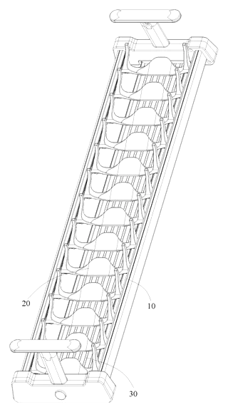
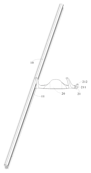
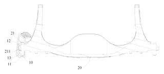
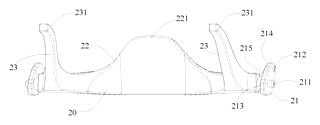
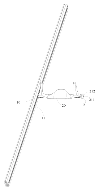
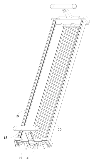
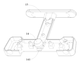
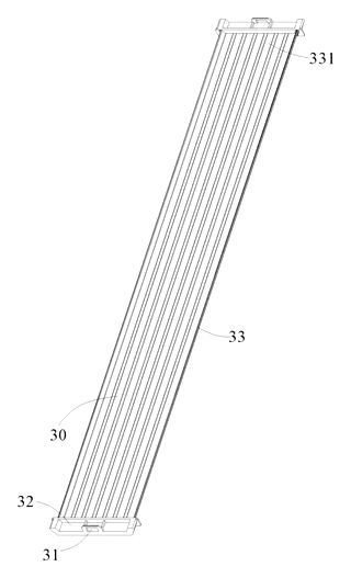
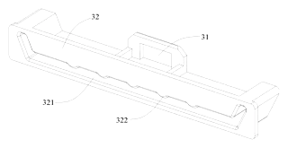
Drawings reproduced from the public patent document for reference.
Frequently asked questions
How does the sliding divider lock?
The divider uses an eccentric cam connector. You rotate the handle on the connector. Because the parts are offset, this rotation moves a guide post along a track while simultaneously pushing a protrusion into a groove on the frame. This locks the divider in place without screws.
Can I remove the drain tray easily?
Yes. The drain tray is attached using a spring-loaded locking pin. You pull the pin outward against the spring tension to disengage it from the tray, allowing you to lift the tray out for cleaning. To reinstall, simply push it back until the pin snaps into place.
Is the plastic safe for food contact?
The patent describes a plastic structure. For US sales, materials must comply with FDA 21 CFR regulations for food contact. We typically recommend using certified PP or ABS grades that are BPA-free and tested for migration limits. Specific material certifications should be confirmed with your supplier.
Does the rack wobble when plates are heavy?
The cam-lock mechanism is designed to provide rigid fixation. Once the protrusion engages the groove, the divider is constrained against lateral movement. Stability depends on the stiffness of the plastic and the precision of the mold. Functional testing during prototyping verifies load-bearing performance.
What sizes are available?
The patent does not specify exact dimensions. Sizes are determined by design requirements. Common countertop widths range from 10 to 18 inches, but custom lengths can be engineered to fit specific sink or counter spaces.
Can this design be made and sold in the US?
The patent is in force in China, but the public record shows no US counterpart. Therefore, this specific patent does not restrict manufacturing or selling in the United States. However, other patents may exist in the kitchen organization field, so a freedom-to-operate review is recommended before mass production.
Are you affiliated with the patent owner?
No. IP2M is an independent design and manufacturing service working from the public patent document.
Request a quote
Click Request a Quote below to see our email address - copy it, or open your email app with a ready-made message. Please mention patent CN118902352B in the subject.
Helpful details to include:
- Your company and channel (kitchenware brand, retail buyer, hospitality supplier)
- Target dimensions (length, width, height) and capacity requirements
- Material preference (PP, ABS, etc.) and color codes
- Features (cutlery holder, silicone feet, specific drain patterns)
- Estimated quantity and target price
- Timeline - when you would like prototypes and the first shipment
You can also reach us at (332) 203-9997.
Page editor: Daniel Chen, Product Research Editor · IP2M
Last updated November 6, 2026. If something on this page looks wrong, email [email protected] and we will check it against the patent.
Interested in building this?
Tell us your target market, quantity and timeline. We reply with options for prototyping, small-batch runs or volume production.
Send your inquiry to
Please put CN118902352B in the subject line and tell us your company, country, estimated quantity and timeline.
Prefer to talk? Call (332) 203-9997.
More product-ready patents
All Home, Kitchen & Cleaning patents →
Home, Kitchen & Cleaning
Self-Wringing Flat Mop with Fold-Away Wringer
Flat mop with a built-in wringer that opens only when you wring and folds flat against the pole when you mop.
Patent CN207734114U
Home, Kitchen & Cleaning
Magnetic Double-Sided Window Cleaner with Dial-Set Magnet Strength
Magnetic window cleaner with a sealed, sliding magnet, dial-set strength for different glass thicknesses and a spring-held idle position.
Patent CN209360543U
Home, Kitchen & Cleaning
Metal Kettle with Magnetic Lid That Stays On When Pouring
Metal teapot/kettle with a magnet-held lid that does not fall off when pouring, and an insulated, vented lid knob.
Patent CN210540477U
Home, Kitchen & Cleaning
Reinforced Disposable Soup Spoon
Disposable soup spoon with a handle-to-bowl rib, stiffened edges and a ring foot to resist breaking.
Patent CN206964482U
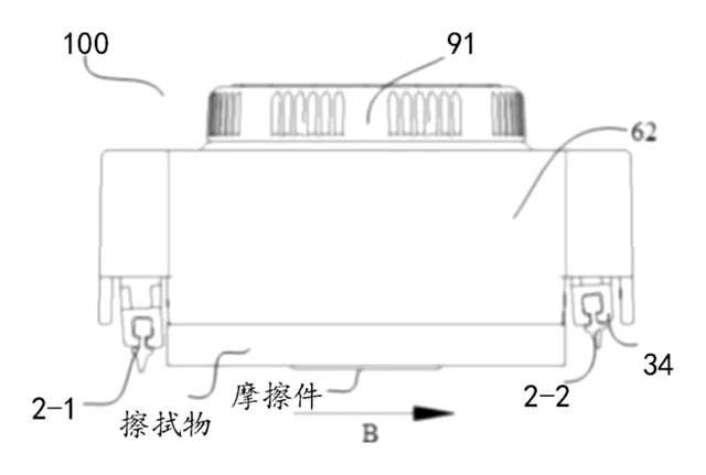
Home, Kitchen & Cleaning
Self-Switching Double-Squeegee Window Cleaner
Cleaning head with two squeegee blades that switch automatically with the direction of movement.
Patent CN212630655U
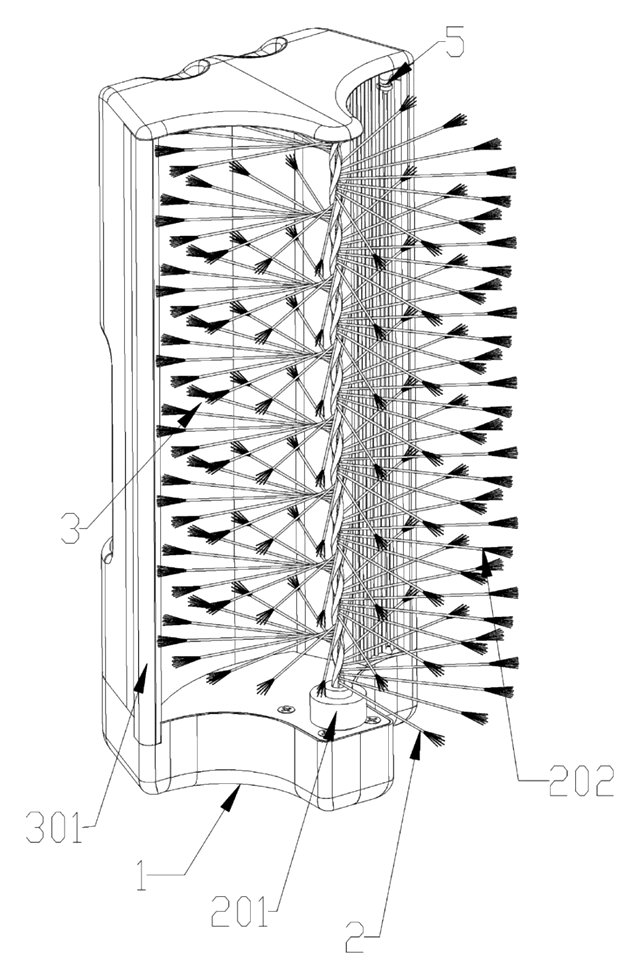
Home, Kitchen & Cleaning
Self-Rinsing Roller Scrub Brush with Dirty-Water Tank
Powered roller brush that rinses and spins its bristles clean inside the body and stores the dirty water.
Patent CN210076909U
Browse by category
- Apparel & Accessories (45)
- Baby & Kids (28)
- Bags & Luggage (16)
- Bath & Personal Care (30)
- Car Accessories (24)
- Furniture, Bedding & Storage (23)
- Garden & Outdoor (31)
- Health & Wellness (13)
- Home, Kitchen & Cleaning (48)
- Lighting (22)
- Packaging & Containers (12)
- Pet Products (11)
- Phone & Camera Accessories (9)
- Retail Display (24)
- School, Office & Art (34)
- Sports & Recreation (44)
- Tools & Workshop (53)
- Toys & Games (22)
This page is based on the public patent document CN118902352B, assigned to Guangdong Tute Precision Hardware Technology Co ltd. IP2M is an independent manufacturing service and is not affiliated with, endorsed by or licensed by the patent owner. Images marked as concept renderings are illustrations, not photos of an existing product. Patent status information is provided for reference only and is not legal advice; confirm freedom to operate for your market before production. Full disclaimer.