At a glance
| Patent number | CN118927187B (application CN202411427372) |
| Type | China invention patent (发明专利) - protects technical solutions and methods |
| Original title | Auxiliary tool for installing downlight protection plate (一种用于筒灯防护板安装的辅助工具) |
| Patent owner | Suzhou Rongwen Kubai Lighting System Co ltd |
| Inventors | Guo Zhengzu, Hou Ye, Jiang Xiao, Guan Jian |
| Filing date | 2024-10-14 |
| Grant date | 2025-01-21 |
| Status (China) | In force - valid until at most 2044-10-14, provided annual fees are paid |
| Patent family | Chinese filings only - no US, European, Japanese, PCT or other filings listed |
| Cited by | 0 later documents |
| Source | Google Patents (search for CN118927187B) |
What the claims cover, in plain language
Claim 1 defines an auxiliary tool comprising a positioning member, a pressing member, and a centering member. The positioning member includes a circular plate with a central platform for holding the downlight’s protective piece. It features a bottom ring plate with cross-grooves containing cross-sliders. These sliders are connected to shaped push plates that move radially to center the protective piece. Guide vertical rods allow displacement plates to move vertically, supporting a central tube that holds the lamp housing barrel. Return springs facilitate the lowering of the central tube. The centering member rotates to drive the cross-sliders, ensuring the protective piece and housing are concentrically aligned before the snap-fit operation.
Dependent Claims describe further details such as sliding columns connecting the centering ring to the sliders, T-shaped grooves for stability, and specific geometries of the arc-shaped rotating plates and baffles that interact with the positioning base.
This is a simplified reading for orientation only. The legal scope is defined by the exact claim wording in the official Chinese document.
What this means for US production
This patent was filed only in China and is currently in force. Making, using, or selling products that fall within the claims of this patent in China requires permission from the patent owner. There is no corresponding US patent application listed in the family.
Two points to settle early:
- Other patents may exist. Lighting assembly tools and downlight structures are a competitive field. While this specific mechanical jig is protected in China, similar centering devices or snap-fit mechanisms might be covered by existing US utility patents held by major lighting manufacturers or tool companies. A freedom-to-operate (FTO) review is recommended before launching a similar tool in the US market.
- Material and Safety Standards. Tools used in electrical environments must meet safety standards regarding insulation and material flammability if they come into contact with live components, though this tool appears designed for assembly rather than direct electrical work.
Customization and manufacturing
What can be customized
| Area | Options |
|---|---|
| Dimensions | Diameter of the placing platform and central tube to match specific downlight sizes (e.g., 2-inch, 4-inch, 6-inch cans). |
| Materials | Aluminum alloy for lightweight durability, or engineering plastics (POM/ABS) for cost-effective mass production. |
| Spring Force | Adjust stiffness of return springs to accommodate different housing weights or snap-fit resistance levels. |
| Surface Finish | Anodized coating for corrosion resistance, or powder coating for color-coded inventory management. |
| Modularity | Interchangeable centering rings to handle various protection plate diameters without changing the whole jig. |
Things to plan for (US market)
- OSHA General Duty Clause: Ensure moving parts (sliders, springs) are guarded or designed to prevent pinch points if used in an industrial setting.
- ANSI B107 Series: While primarily for hand tools, general ergonomic and safety principles apply to assembly jigs used by operators.
- RoHS/REACH Compliance: If exporting materials, ensure metals and plastics meet environmental regulations for restricted substances, particularly if the tool touches electronic components.
How a project runs
- Inquiry - Specify downlight model dimensions, desired throughput, and material preferences.
- Design Adaptation - Modify the central tube diameter and slider travel range to fit the target fixture.
- Prototype - CNC machine a single unit to test alignment accuracy and snap-fit ease.
- Validation - Perform cycle testing to ensure springs and sliders do not fatigue prematurely.
- Production - Injection molding for plastic parts, stamping/machining for metal bases, and assembly.
Quantities & timeline
Tooling costs depend on whether parts are machined or molded. Injection molds for the centering ring and sliders require lead times of 4-6 weeks. Machined prototypes can be ready in days. Certification tests are minimal unless electrical safety is involved. Send us your downlight specifications, quantity needs, and material preferences and we will reply with options.
Patent drawings
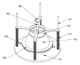
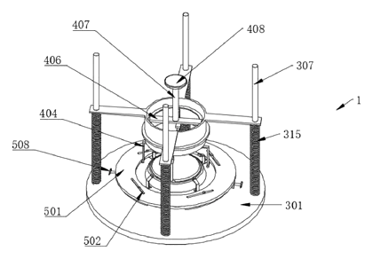
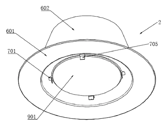
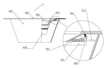
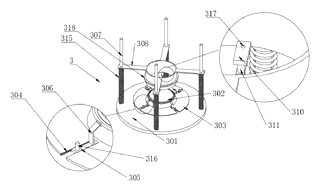
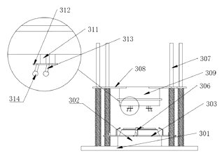
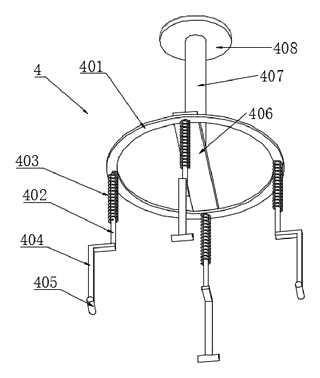
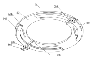
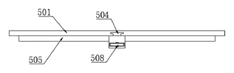
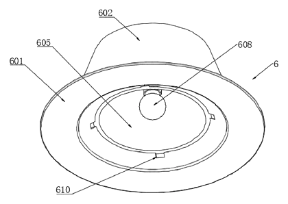
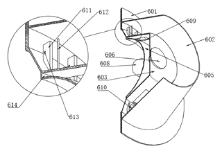
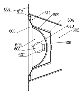
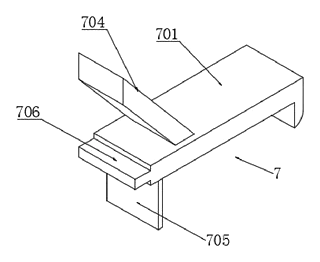
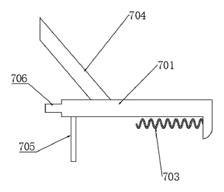
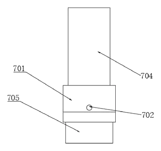
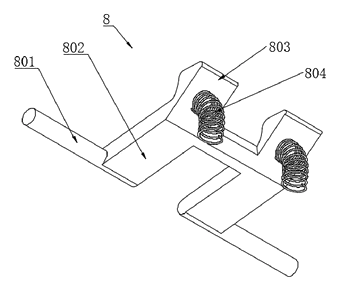
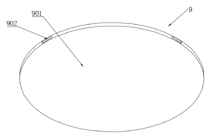
Drawings reproduced from the public patent document for reference.