
Patent CN119289230B
Updated November 8, 2026Portable High-Precision Mobile Pan-Tilt Device with Guide Rail Adjustment
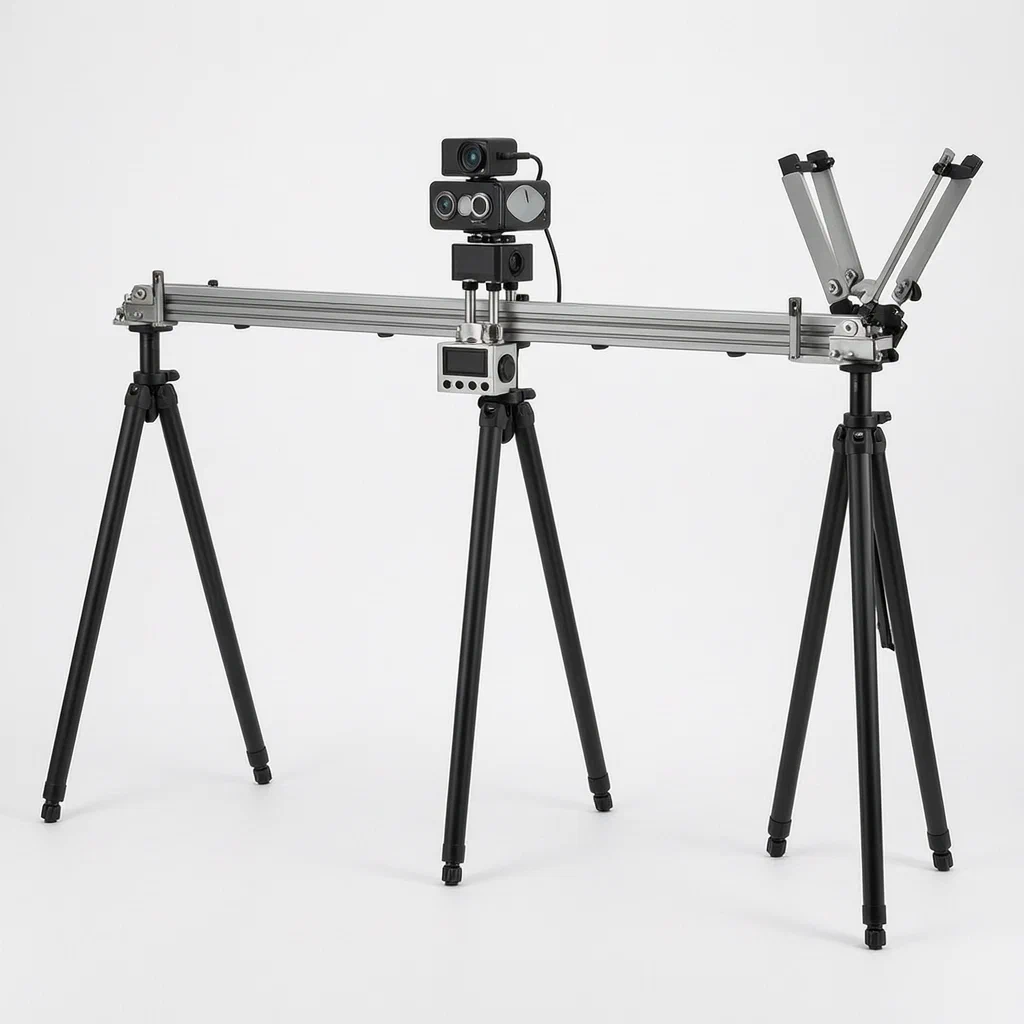
Standard camera gimbals often struggle with stability during long linear movements or in windy outdoor conditions. This patent describes a portable high-precision mobile pan-tilt device that uses a dedicated guide rail adjustment base rather than a simple tripod mount. By integrating a vertical axis adjustment handle and Q1 quick-release interfaces, it allows for precise leveling and rapid deployment. The core innovation lies in its mechanical stabilization: a reinforcement component with bidirectional lead screws clamps the image collector securely to the moving head, while magnetic sensors along the rail track ensure accurate positioning. For outdoor use, the system can deploy aerodynamic folding wings via double-headed cylinders to reduce wind-induced vibration, maintaining image clarity even when the unit is moving rapidly.
- China invention patent - in force
- No filings outside China
- Camera & video production accessories
- Aluminum CNC parts, PEEK gears, ABS housings
Splat! What let you down?
🛤️
Guide Rail Base
Adjustable support base with vertical axis handle for precise leveling and height control.
⚡
Quick Release Mounts
Q1 and F38 quick-release interfaces allow fast swapping of heads and cameras.
🔩
Mechanical Reinforcement
Bidirectional lead screw brackets clamp the image collector for enhanced stability.
🌬️
Wind Stabilization
Optional folding wing plates deployed by cylinders reduce vibration from outdoor wind.
Bring this product to market
- ✓ Patent review Patent family and legal status reviewed in the relevant jurisdictions.
- 2 Product brief · now How it works, uses and options written up
- 3 Prototype First samples for buyers to review
- 4 Pilot run Small first batch for launch customers
- 5 Volume production Repeat orders at scale
Buyer interest
– of 100 buyers needed to start prototyping
One click, no sign-up. Each vote is one real visitor, and products with the most interest go to prototyping first.
Build team: no members yet. Need a partner, co-funding or skills to build this? Join and we introduce the team once it forms.
Patent Rights & Team Participation
Before joining a development team, participants should ensure they have the necessary rights or authorization to participate in the project.
Participation is generally appropriate where:
- You own the relevant patent rights or have obtained permission or a license from the rights holder.
- The relevant patent rights have expired or have been legally invalidated in the jurisdictions where the planned activities will take place.
- The planned development, manufacturing, and commercialization activities have been independently assessed and do not infringe applicable patent rights in the relevant jurisdictions.
Important: Being located outside a country where a patent is protected does not automatically exempt you from patent infringement risks. Patent rights may apply based on where development, manufacturing, use, sale, or import activities take place.
IP2M does not grant any patent license or authorization through team participation. Joining a project does not provide permission to use, manufacture, or commercialize patented technology.
The problem
Traditional handheld gimbals or static tripod-mounted pan-tilt heads face limitations when performing long, linear tracking shots. Maintaining a perfectly straight path over distance requires significant manual effort or expensive slider rigs. Furthermore, when these devices are used outdoors, wind resistance against the camera body and lens creates micro-vibrations that degrade image quality, especially during rapid movement. Standard solutions lack integrated mechanisms to actively counteract this wind pressure or to provide precise, repeatable linear guidance without complex external rigging.
The solution
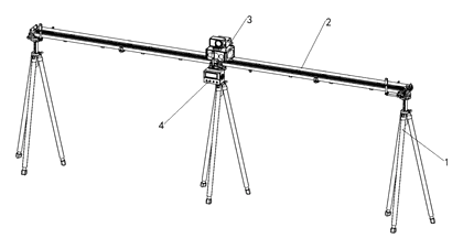
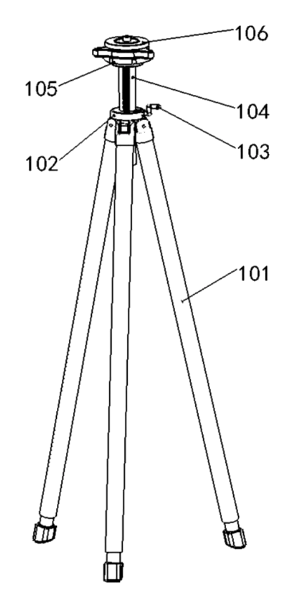
- A guide rail adjustment base (1) serves as the foundation, featuring a support foot (101) and a base body (102) connected by a hinge. A vertical axis adjustment handle (103) controls the angle and position of the internal vertical axis (104).
- The top of the vertical axis holds a Q1 quick-release base (105) and plate (106), allowing the entire upper assembly to be detached or mounted quickly.
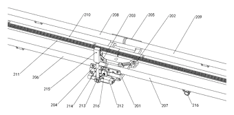
- Mounted on the Q1 plate is the pan/tilt guide rail assembly (2). This includes an intermediate guide rail base (201) with front and rear left/right guide rails (206-209) and a PEEK rack (210).
- The image acquisition module (3) consists of a pan-tilt body (301) with guide wheels (302) that slide along the rails. Inside, a motor (303) drives a PEEK gear (304) that meshes with the rack, moving the head linearly.
- A reinforcement component (5) secures the camera. It uses external brackets (501) and first/second reinforcement brackets (503, 504) driven by bidirectional lead screws (502) to clamp firmly onto the pan-tilt body surface.
- Calibration lights (215) are mounted on adjustable frames (213) along the rails, controlled by a separate calibration light control box (4) with a display screen (402).
Who it is for
- Professional videographers needing smooth, linear tracking shots without setting up heavy dolly tracks.
- Film production assistants who require rapid deployment and teardown of camera movement systems between scenes.
- Industrial inspection teams using automated pan-tilt heads for scanning large structures where stability and precision are critical.
- Outdoor content creators facing windy conditions who need active stabilization beyond standard electronic gimbal correction.
How it works
The main parts
| No. | Part | What it does |
|---|---|---|
| 1 | Guide Rail Adjustment Base | Provides height and angle adjustment; houses the vertical axis. |
| 101-106 | Support Foot & Quick Release | Hinged base with Q1 interface for mounting the rail assembly. |
| 2 | Pan/Tilt Guide Rail Assembly | The track structure with PEEK rack and magnetic sensors. |
| 201-209 | Intermediate Base & Rails | Front/rear left/right rails guide the moving head. |
| 3 | Image Acquisition Module | The moving pan-tilt head carrying the camera. |
| 301-304 | Body, Motor & Gear | Motor drives PEEK gear along the PEEK rack for linear motion. |
| 5 | Reinforcement Component | Lead-screw driven brackets clamp the camera securely. |
| 4 | Calibration Light Control Box | Controls brightness and status of the rail-mounted lights. |
Operating Steps
- Setup: Place the support foot (101) on the ground. Use the vertical axis adjustment handle (103) to level the base body (102).
- Mounting: Attach the pan/tilt guide rail assembly (2) to the Q1 quick-release plate (106). Snap the image acquisition module (3) onto the rails.
- Stabilization: Turn the first bidirectional lead screw (502) to extend the first and second reinforcement brackets (503, 504) against the pan-tilt body (301), locking the camera mount.
- Movement: Activate the motor (303). The PEEK gear (304) rotates, engaging the PEEK rack (210) to move the head smoothly along the guide rails (206-209).
- Wind Compensation (Optional): If outdoors, activate the double-headed cylinder (513). It extends support rods (515) to unfold the folding wing plates (516), creating an aerodynamic profile that pushes down against wind lift.
Applications
Film and Video Production
Directors of photography use this system for “bullet time” effects or smooth linear reveals. The guide rail ensures the camera moves in a perfect straight line relative to the subject, eliminating the arc common with handheld gimbals.
Industrial Inspection
Engineers inspecting large bridges or buildings attach high-resolution cameras to the module. The reinforcement brackets keep the lens steady against vibrations from nearby machinery, while the rail allows systematic scanning of surfaces.
Outdoor Wildlife Filming
Documentaries often require long-distance tracking of animals. The wind-stabilizing wings help maintain shot integrity in open fields where gusts would otherwise blur images taken by standard tripods.
Event Broadcasting
For sports or concerts, operators can set up temporary linear tracks around stages. The quick-release Q1 and F38 mounts allow rapid reconfiguration if the camera needs to switch lenses or positions mid-event.
Where it is less suitable
- Handheld Walking Shots: This is a rail-based system; it cannot be carried freely like a handheld gimbal.
- Vertical Portrait Mode: The design focuses on horizontal linear movement; vertical tracking requires different rigging.
- Extreme Heavy Lenses: While reinforced, the motor and rail load capacity are designed for standard cinema or DSLR setups, not massive broadcast lenses.
Patent & Production
At a glance
| Patent number | CN119289230B (application CN202411723193) |
| Type | China invention patent (发明专利) - protects product method and structure |
| Original title | Portable High-Precision Mobile Pan-Tilt Device (一种便携式高精度移动云台装置) |
| Patent owner | Wuxi Feilike Technology Co ltd |
| Inventors | Li Yue |
| Filing date | 2024-11-28 |
| Grant date | 2025-04-29 |
| Status (China) | In force - valid until at most 2044-11-28, provided annual fees are paid |
| Patent family | Public record shows Chinese filings only - no US, European, Japanese, PCT or other filings listed |
| Cited by | 0 later documents |
| Source | Google Patents (search for CN119289230B) |
What the claims cover, in plain language
Claim 1 defines a portable high-precision mobile pan-tilt device comprising a guide rail adjustment base (1) and a terminal control tablet. The base features a support foot (101) hinged to a base body (102) with a vertical axis adjustment handle (103). A vertical axis (104) slides within the base, topped by a Q1 quick-release base (105) and plate (106). On the plate sits a pan/tilt guide rail assembly (2) which carries an image acquisition module (3) and a calibration light control box (4). The image module includes a reinforcement component (5) made of an external bracket (501) and bidirectional lead screws (502) that drive first and second reinforcement brackets (503, 504) to clamp the pan-tilt body.
Claim 2 details the guide rail assembly (2), specifying an intermediate guide rail base (201) fixed to the Q1 plate. It includes rack locking blocks (202, 203), front and rear guide rails (206-209), and a PEEK rack (210) on a rack base (211). Magnetic sensor sheets (216) are attached to the bottoms of the rails. Calibration lamp holders (212, 219, 225) and limit blocks (221, 224) are also described.
Claim 3 describes the image acquisition module (3), including the pan-tilt body (301) with guide wheels (302) sliding on the rails. An internal motor (303) drives a PEEK gear (304) meshing with the rack. It features an F38 quick release (306) for the image collector (305), a battery pack (308), and front/rear sensors (309, 311) with covers.
Claims 4-7 cover the calibration light control box (4) with display and switches, the reinforcement component’s rotating bases and springs, buffer guide wheels with displacement sensors, and the double-headed cylinder (513) system that deploys folding wing plates (516) for wind stability.
This is a simplified reading for orientation only. The legal scope is defined by the exact claim wording in the official Chinese document.
What this means for US production
This patent was filed in China and is currently in force. The public record shows no US or other foreign counterpart. Making or selling this specific design in China requires the owner’s permission.
Two points to settle early:
- Other patents may exist. Camera movement systems, gimbals, and slider technologies are heavily patented globally. Companies like DJI, Zhiyun, and various US optical firms hold broad patents on stabilization algorithms and mechanical mounts. A freedom-to-operate (FTO) review is essential to ensure the specific combination of the Q1/F38 quick-release integration, the PEEK rack-and-pinion linear drive, and the wind-wing mechanism does not infringe on existing US intellectual property.
- Material Specifications. The patent explicitly mentions PEEK (Polyether ether ketone) for the rack and gear. Sourcing certified PEEK components and ensuring tight tolerance fits for the bidirectional lead screws will impact manufacturing complexity and cost.
Customization and manufacturing
What can be customized
| Area | Options |
|---|---|
| Rail Length | Modular sections to adjust total travel distance |
| Load Capacity | Motor torque and gear ratio adjustments for heavier lenses |
| Materials | Aluminum CNC vs. high-strength polymer housings |
| Control Interface | Bluetooth/Wi-Fi app integration vs. physical button control |
| Lighting | RGB calibration lights for color matching vs. white light |
| Wing Mechanism | Manual deployment vs. automated cylinder-driven wings |
Things to plan for (US market)
- FCC Part 15: If the device includes wireless control (Bluetooth/Wi-Fi) or emits radio frequencies from its motors/sensors, it must comply with FCC regulations for unintentional radiators.
- UL 62368-1: Safety standard for audio/video information and communication technology equipment, covering battery safety and electrical insulation.
- UN 38.3: Transport testing for the lithium-ion battery packs included in the image acquisition module.
- California Prop 65: Screening for chemicals in plastics, coatings, and solder materials used in the PCB assembly.
How a project runs
- Inquiry - Define rail length, payload weight, and desired automation level.
- Design - CAD modeling of the CNC aluminum base and injection-molded plastic components.
- Prototype - 3D-printed fit checks for the lead screw assemblies and CNC machined housing samples.
- Pilot Run - Assembly of electronics, motor calibration, and field testing for wind stability.
- Production - Mass production of molded parts, CNC machining of rails, and final assembly.
Quantities & timeline
Tooling for the complex reinforcement brackets and the dual-cylinder wing mechanism requires multiple molds. CNC machining time for the guide rails is significant due to the precision required for the PEEK rack interface. Electronics assembly involves careful routing of sensor cables. Send us your target payload, rail length, and quantity requirements and we will reply with options.
Production notes
Tooling and process
The device typically relies on a mix of aluminum CNC machining for the structural base and rails, and PC or ABS injection molding for the lighter housings and control boxes. Electronics assembly integrates the main control board and sensors. Motor assembly and battery pack assembly are critical sub-processes.
Cost drivers
CNC time is typically a major driver due to the precision needed for the guide rails. Mold count increases with the multi-part reinforcement brackets and wing plates. Finish quality on the aluminum parts affects both aesthetics and corrosion resistance.
Prototyping path
We typically start with a 3D-printed fit sample to verify the lead screw mechanics. Proceed to CNC housing prototypes for structural testing. Conduct a magnet pull test on the quick-release interfaces before finalizing tooling.
What we would change before tooling
We would likely simplify the hinge boss and pivot wear points on the base to improve longevity. Ensuring consistent spring fatigue and rate consistency in the reinforcement brackets is vital for uniform clamping pressure.
Common failure points
Shaft and bearing alignment in the vertical axis can cause jitter. Wire routing and strain relief near the moving head is a risk area. Adhesive failure on sensor covers could compromise environmental sealing.
Patent drawings
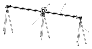
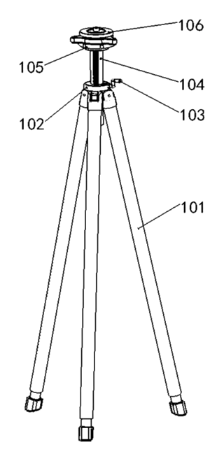
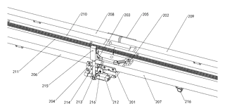
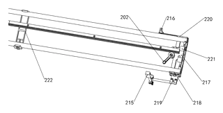
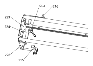
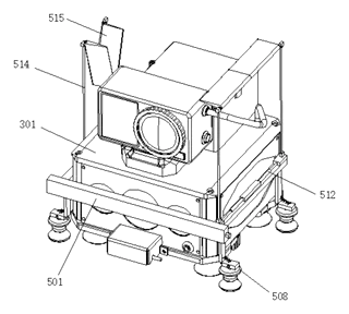
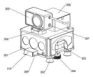
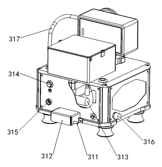
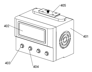
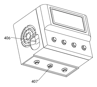
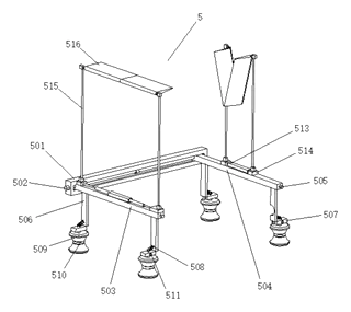
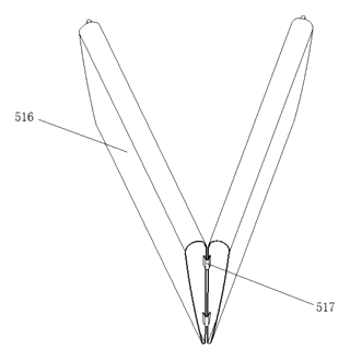
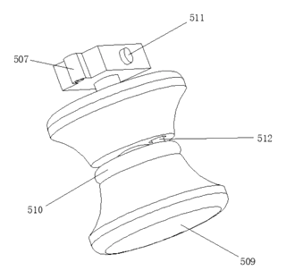
Drawings reproduced from the public patent document for reference.
Frequently asked questions
How does this differ from a standard gimbal?
Unlike a handheld gimbal that balances a camera in free space, this device moves the camera along a fixed linear track (the guide rails). This provides a mechanically constrained, perfectly straight path for tracking shots, reducing the “jello effect” common in handheld stabilization.
What is the “wind stabilization” feature?
The patent describes an optional reinforcement component with double-headed cylinders. When activated, these cylinders push out folding wing plates. These plates act like spoilers, generating downward pressure to counteract wind lift, keeping the camera stable during outdoor shoots.
Is it compatible with my existing camera accessories?
Yes. The design uses industry-standard Q1 and F38 quick-release interfaces. This allows you to mount the pan-tilt head onto the base quickly and attach cameras or lenses using standard quick-release plates compatible with those formats.
Why are PEEK gears and racks used?
PEEK (Polyether ether ketone) is a high-performance engineering plastic known for its low friction, high strength, and dimensional stability. Using PEEK for the rack and gear reduces noise, minimizes wear, and ensures smooth, precise linear movement compared to standard nylon or metal gears.
How long does the battery last?
The patent includes a battery pack but does not specify runtime. Battery life depends on the motor load, usage of the calibration lights, and the power draw of the attached camera. Typical runtimes for similar mobile rail systems range from 2 to 4 hours, confirmed on prototypes.
Can I control it remotely?
The system includes a terminal control tablet interface and a debug port. While the patent focuses on the mechanical structure, the presence of a main control board suggests potential for wired or wireless remote control integration, depending on the final firmware implementation.
Can this design be made and sold in the US?
The patent is in force in China. The public record shows no US counterpart, so it does not restrict the design in the US based solely on this patent. However, camera movement technologies are widely patented. We recommend a freedom-to-operate check to ensure no other US patents cover the specific combination of the rail drive and wind-wing mechanism.
Are you affiliated with the patent owner?
No. IP2M is an independent design and manufacturing service working from the public patent document.
Request a quote
Click Request a Quote below to see our email address - copy it, or open your email app with a ready-made message. Please mention patent CN119289230B in the subject.
Helpful details to include:
- Your company and channel (film equipment rental, industrial inspection firm, video production studio)
- Desired rail length and maximum camera/lens weight
- Feature preferences (wind wings, calibration lights, remote control)
- Estimated quantity and target price
- Timeline - when you would like prototypes and the first shipment
You can also reach us at (332) 203-9997.
Page editor: Daniel Chen, Product Research Editor · IP2M
Last updated November 8, 2026. If something on this page looks wrong, email [email protected] and we will check it against the patent.
Interested in building this?
Tell us your target market, quantity and timeline. We reply with options for prototyping, small-batch runs or volume production.
Send your inquiry to
Please put CN119289230B in the subject line and tell us your company, country, estimated quantity and timeline.
Prefer to talk? Call (332) 203-9997.
More product-ready patents
All Phone & Camera Accessories patents →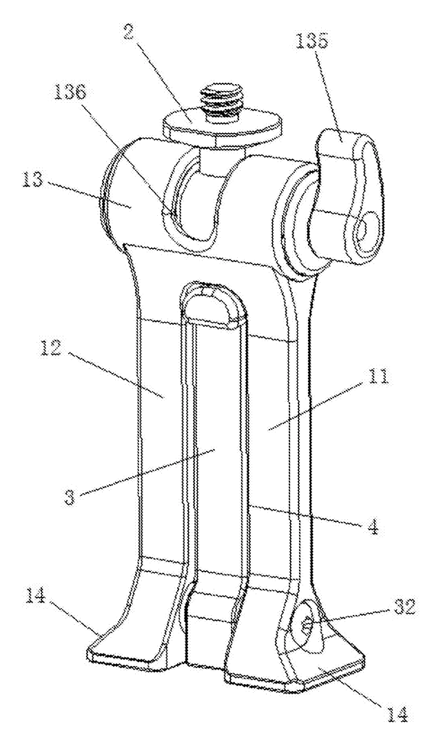
Phone & Camera Accessories
Phone Clip Mount with Fold-Out Stand Leg
Phone clamp adapter with a ball-joint top, a dovetail base for tripod clamps and a fold-out desk leg.
Patent CN207394276U
Stands & Mounts
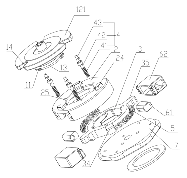
Manual Quick-Release Connector for Camera Equipment
Quick-release camera mount using a rotating driver and spring-loaded locking grooves.
Patent CN215294199U
Phone & Camera Accessories
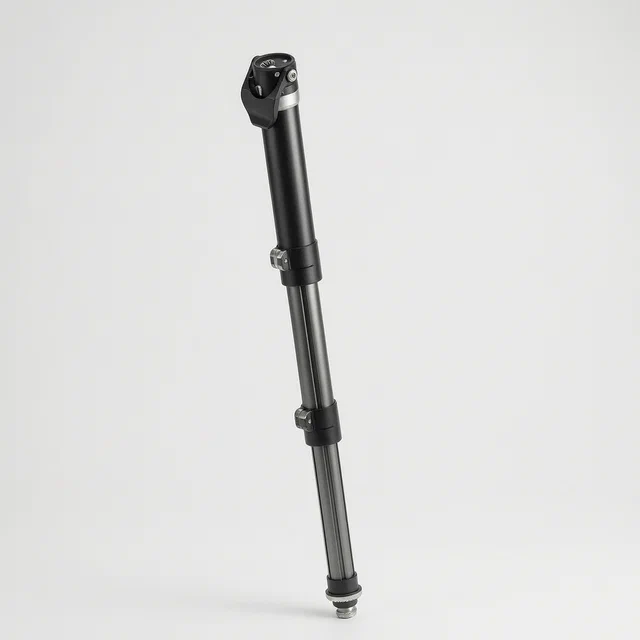
Extendable Support Leg and Monopod with Single-Knob Locking
Three-section monopod leg locked and released from one top knob via a transmission rod.
Patent CN113090903B
Phone & Camera Accessories
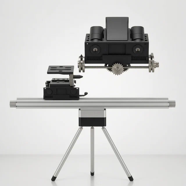
Remote-Controlled Outdoor Photography Tripod with Movable Lens Mount
Motorized tripod with a remote-driven camera seat and a sliding multi-lens mount.
Patent CN118328254B
Phone & Camera Accessories
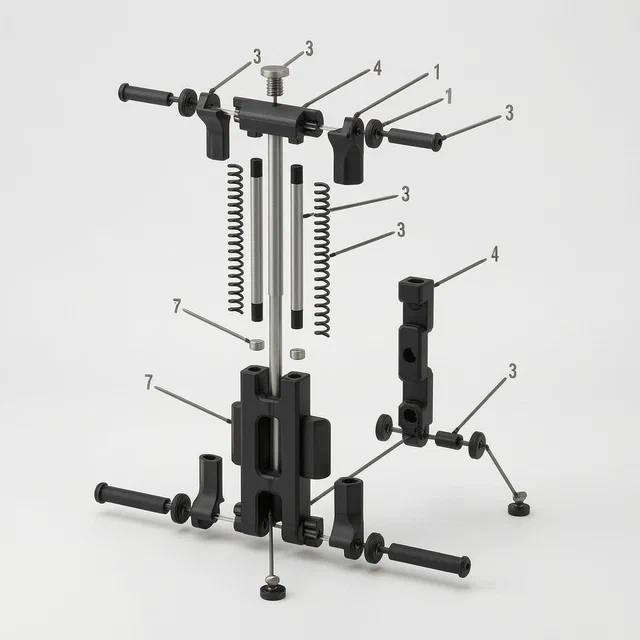
Foldable Multifunctional Mobile Phone Clip with Rotating Support Feet
Foldable phone clip with rotating tripod-compatible feet and 1/4-inch screw mounts.
Patent CN207112268U
Phone & Camera Accessories
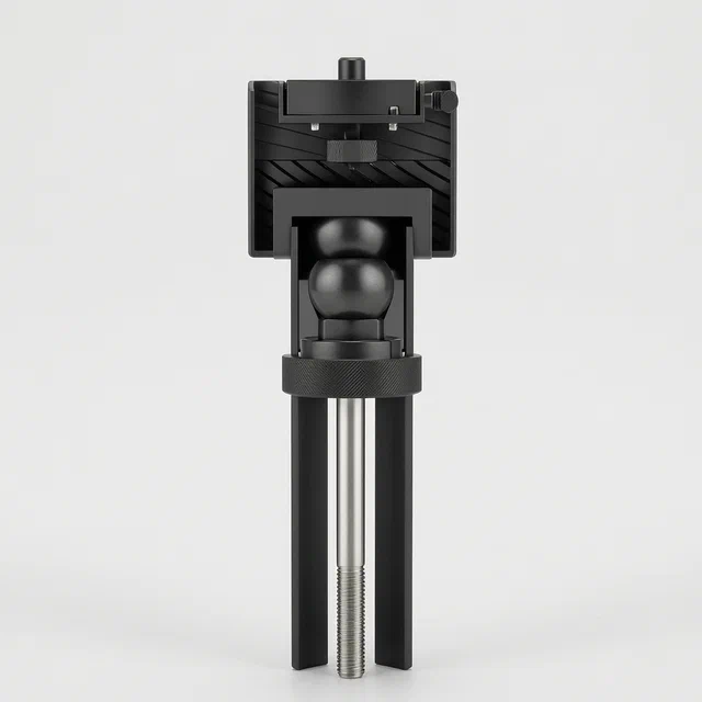
One-Touch Locking Ball Head Mount for Cameras and Equipment
Single-knob ball head mount that locks the ball and secures the device in one rotation.
Patent CN220930728U
Browse by category
- Apparel & Accessories (51)
- Baby & Kids (30)
- Bags & Luggage (17)
- Bath & Personal Care (33)
- Car Accessories (27)
- Furniture, Bedding & Storage (25)
- Garden & Outdoor (34)
- Health & Wellness (15)
- Home, Kitchen & Cleaning (52)
- Lighting (25)
- Packaging & Containers (13)
- Pet Products (12)
- Phone & Camera Accessories (10)
- Retail Display (27)
- School, Office & Art (38)
- Sports & Recreation (49)
- Tools & Workshop (57)
- Toys & Games (24)
This page is based on the public patent document CN119289230B, assigned to Wuxi Feilike Technology Co ltd. IP2M is an independent manufacturing service and is not affiliated with, endorsed by or licensed by the patent owner. Images marked as concept renderings are illustrations, not photos of an existing product. Patent status information is provided for reference only and is not legal advice; confirm freedom to operate for your market before production. Full disclaimer.