
Patent CN205391005U
Updated October 26, 2026Self-Dumping Coffee Brewing Unit with Hydraulic Piston and Filter Screens
Conventional automatic coffee makers rely on a dedicated push rod or scraper to knock the spent coffee puck out of the brew group after extraction. That extra actuator adds parts, takes up space inside the chassis, and introduces another point of mechanical failure. This design removes the ejector entirely. The brewing chamber slides along a guide bar driven by a motor and gear-rack set, while a hydraulic piston presses against it from the opposite side. Both faces that touch the coffee carry filter screens. When brewing ends, the motor pulls the chamber back and a return spring draws the piston away. The gap between the two screens opens, and the wet grounds simply fall straight down into the waste bin. Fewer moving parts mean a smaller footprint and a simpler assembly sequence for manufacturers scaling up production.
- China utility model - withdrawn
- No filings outside China
- Kitchen appliances
- Motor-driven slide, hydraulic piston, metal filter screens
Splat! What let you down?
☕
Gravity puck ejection
The chamber and piston retract in opposite directions so spent grounds drop without any push rod or scraper.
⚙️
Gear-and-rack drive
A motor turns two meshing gears that engage a toothed sleeve on the chamber for precise left-right travel.
💧
Internal water channel
Hot water flows through a passage inside the piston, regulated by a spring-loaded check valve before entering the brew space.
📐
Compact layout
Removing the ejector mechanism allows the entire brew group to fit into a smaller machine body.
Bring this product to market
- ✓ Patent vetted China-only family and legal status checked
- 2 Product brief · now How it works, uses and options written up
- 3 Prototype First samples for buyers to review
- 4 Pilot run Small first batch for launch customers
- 5 Volume production Repeat orders at scale
Buyer interest
– of 100 buyers needed to start prototyping
One click, no sign-up. Each vote is one real visitor, and products with the most interest go to prototyping first.
Build team: no members yet. Need a partner, co-funding or skills to build this? Join and we introduce the team once it forms.
The problem
In most automatic espresso and drip coffee machines, the brew group compresses ground coffee between two surfaces to extract flavor under pressure. Once the cycle finishes, the wet puck sticks to one of those surfaces. To clear it, manufacturers add a separate push rod, scraper arm, or secondary cam driven by another motor or linked mechanically to the main drive. According to the patent, these extra components occupy valuable space inside the machine housing, complicate the assembly line, and increase the chance of jamming when coffee oils build up over time. For brands trying to shrink their countertop models or reduce warranty claims tied to the ejection mechanism, the traditional push-rod approach is a bottleneck.
The solution
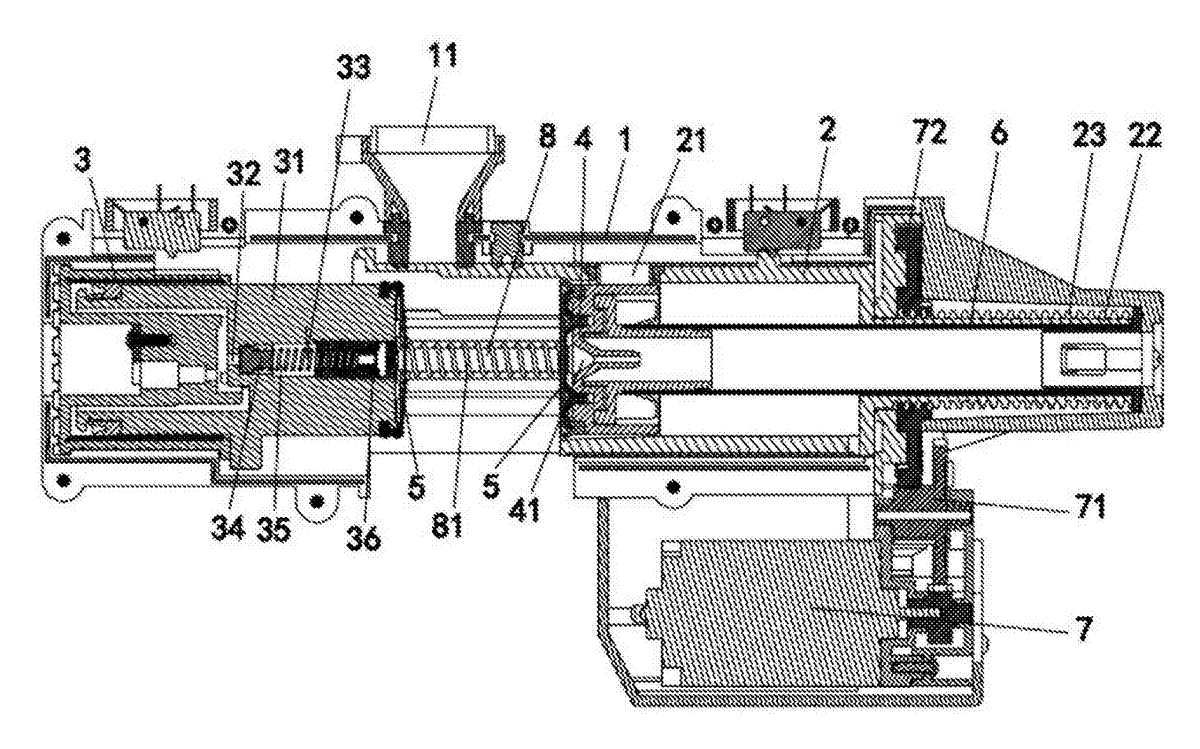
This brewing device replaces the push rod with coordinated retraction of two opposing parts. A brewing chamber (2) slides horizontally along a slide bar (6) mounted inside the machine body (1). Directly opposite the chamber, a hydraulic cylinder (3) houses a piston (31). The end face of the fixed brewing seat (4) and the end face of the piston each carry a filter screen plate (5). Hot water enters through a flow channel (32) drilled inside the piston, passing a check valve (33) that holds pressure until the correct brewing force is reached.
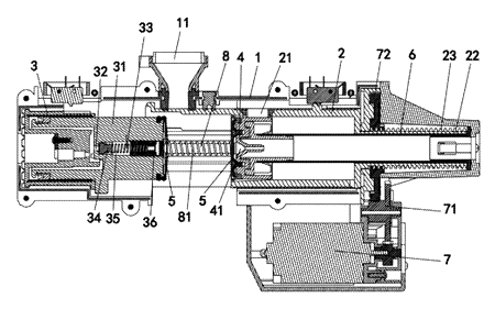
After extraction, the drive motor reverses, pulling the brewing chamber away from the brewing seat. Simultaneously, a back-moving spring (81) pushes the piston back along its own guide rod (8). As both surfaces separate, the coffee puck loses support on either side and falls by gravity into the drip tray below. No additional actuator contacts the grounds.
Who it is for
- Countertop appliance brands developing fully automatic espresso machines who want to advertise a simpler, fewer-parts brew group to differentiate from competitors using complex linkage ejection systems.
- Office coffee service equipment suppliers looking for a brew mechanism that requires less frequent cleaning intervention, since there is no push rod accumulating coffee residue.
- OEM contract manufacturers producing white-label coffee makers for retail chains, seeking a compact internal module that fits into narrower plastic housings without redesigning the chassis around an ejector motor.
- Vending machine integrators building hot-beverage dispensers where vertical space inside the cabinet is limited and every millimeter saved on the brew group allows a larger bean hopper or water tank.
How it works
The main parts
| No. | Part | What it does |
|---|---|---|
| 1 | Machine body | Houses the inner cavity and supports all components. |
| 2 | Brewing chamber | Slides left and right; receives coffee powder through the powder input port (21) aligned with the powder funnel (11). |
| 3 | Hydraulic cylinder | Holds the piston and directs pressurized hot water. |
| 4 | Brewing seat | Fixed in the middle of the cavity; carries the brew head (41) and one filter screen plate. |
| 5 | Filter screen plates | Mounted on both the brewing seat end face and the piston end face to retain grounds during extraction. |
| 6 | Slide bar | Guides the brewing chamber’s horizontal movement. |
| 7 | Motor | Drives the first gear (71), which meshes with the second gear (72). |
| 22 | Sleeve | Attached to the brewing chamber; outer surface has tooth bars (23) engaged by the second gear. |
| 31 | Piston | Moves inside the cylinder to seal the chamber; contains the flow channel. |
| 32 | Flow channel | Internal passage in the piston delivering water to the brewing chamber. |
| 33 | Check valve | Composed of a plug (34), spring (35), and adjusting nut (36); opens only when water pressure exceeds the spring force. |
| 8 | Guide rod | Keeps the piston aligned during its forward and backward stroke. |
| 81 | Back-moving spring | Sits on the guide rod between the piston face and the brewing seat to return the piston after brewing. |
Brewing and dumping cycle
- Loading - The motor (7) rotates forward. The first gear (71) drives the second gear (72), which engages the tooth bars (23) on the sleeve (22). The brewing chamber (2) slides along the slide bar (6) until the powder input port (21) aligns with the powder funnel (11). Ground coffee falls into the chamber.
- Sealing - The hydraulic cylinder (3) activates. Pressurized hot water enters the flow channel (32). Before the check valve (33) opens, the water pressure pushes the piston (31) forward along the guide rod (8). The piston tip enters the brewing chamber, compressing the grounds between the two filter screen plates (5) and sealing the space completely.
- Extraction - As pressure rises further, the water forces the plug (34) against the spring (35), opening the check valve. Hot water flows through the channel into the sealed chamber, extracting the coffee. The spring tension can be tuned by threading the adjusting nut (36) deeper or shallower.
- Dumping - When brewing finishes, the motor reverses, pulling the chamber back along the slide bar. At the same time, the back-moving spring (81) pushes the piston back along the guide rod. Both filter screens move apart. The wet coffee puck, no longer held by either surface, drops straight down out of the machine body into the waste container.
Applications
Compact home espresso machines
Home users often have limited counter space. By eliminating the push rod and its associated linkage, the overall width of the brew group shrinks. Appliance designers can wrap a tighter plastic shell around the mechanism, resulting in a machine that fits between kitchen cabinets more easily while still offering fully automatic grinding, tamping, and brewing.
Office breakroom coffee stations
In shared office environments, machines run dozens of cycles daily. Push rods accumulate sticky coffee oils and require regular manual cleaning to prevent jams. Because this design relies solely on the separation of two flat filter screens for puck release, there are fewer crevices for residue to build up, reducing maintenance frequency for facility managers.
Hotel room single-serve dispensers
Hospitality brands installing automated coffee makers directly into guest rooms need quiet, reliable units that rarely malfunction. A simpler mechanical path with one motor driving a gear train, rather than coordinating multiple actuators for ejection, lowers the probability of a breakdown that would trigger a maintenance call during a guest’s stay.
Commercial vending kiosks
Vending operators prioritize uptime. The self-dumping action ensures the spent puck clears the brew area consistently without relying on a secondary scraper that might bend or wear out after thousands of cycles. The adjustable check valve also lets operators tune the extraction pressure for different bean types across various kiosk locations.
Where it is less suitable
- Manual or semi-automatic espresso setups - Barista-oriented machines where the user handles the portafilter do not need an automated sliding chamber or hydraulic piston.
- Cold brew or steeping devices - The high-pressure hydraulic sealing and rapid retraction cycle are engineered specifically for hot extraction; cold brew requires long soak times without pressurized water injection.
- Machines using paper pods or capsules - Capsule systems pierce and discard a sealed container, making a loose-powder sliding chamber and dual filter screens unnecessary.
Frequently asked questions
How do the coffee grounds actually drop out?
After brewing, the motor reverses to pull the sliding chamber back along its guide bar. At the same time, the return spring pushes the hydraulic piston away from the chamber. Because both the brewing seat and the piston face have flat filter screens holding the puck, separating them removes all support. The wet grounds simply fall straight down into the waste bin below, requiring no scraper or push rod.
Can the brewing pressure be adjusted?
Yes. Inside the piston, the water flows through a channel blocked by a check valve made of a plug, a spring, and a threaded adjusting nut. By turning the nut, you change how much the spring compresses against the plug. This sets the exact water pressure required to force the valve open and begin extraction, allowing tuning for different coffee roasts or grind sizes.
What drives the chamber back and forth?
A single electric motor turns a small first gear, which meshes with a larger second gear. That second gear engages a row of teeth molded or machined onto the outer surface of a sleeve attached to the brewing chamber. Reversing the motor polarity switches the direction of travel along the slide bar.
Is the hydraulic cylinder filled with oil?
Despite the name used in the translated patent text, the cylinder uses the incoming hot water itself as the hydraulic medium. The pressurized water pushes the piston forward to seal the chamber before the check valve opens to let that same water flow through the coffee grounds.
What materials are needed for the filter screens?
The patent specifies filter screen plates but does not list the exact alloy. For production, food-grade stainless steel is standard for hot coffee extraction to resist corrosion and withstand repeated thermal cycling. The mesh aperture size is determined during the design phase based on whether the machine targets fine espresso or coarser grinds.
Does this mechanism work for pre-ground coffee only?
The patent describes the brewing chamber receiving powder through an input port aligned with a funnel on the machine body. It covers the extraction and dumping phases. Integration with an upstream grinder is a system-level design choice handled during engineering, but the brew group itself accepts whatever ground coffee is delivered to that funnel.
Can this design be made and sold in the US?
The patent was filed only in China and was withdrawn when the owner abandoned the patent right effective 2019-05-14, so it does not restrict the design in the US or in China. Automatic coffee brew groups may be covered by other US patents - see Patent & Production - so we recommend a freedom-to-operate check before volume production.
Are you affiliated with the patent owner?
No. IP2M is an independent design and manufacturing service working from the public patent document.
Request a quote
Click Request a Quote below to see our email address - copy it, or open your email app with a ready-made message. Please mention patent CN205391005U in the subject.
Helpful details to include:
- Your company and channel (appliance brand, vending operator, hospitality supplier, contract manufacturer)
- Target beverage type (espresso, lungo, drip) and chamber volume requirements
- Material preferences for the piston, chamber, and filter screens
- Required certifications (UL, NSF, FDA compliance documentation)
- Estimated quantity and target price
- Timeline - when you would like samples and the first shipment
You can also reach us at (332) 203-9997.
Explore this product
Interested in building this?
Tell us your target market, quantity and timeline. We reply with options for prototyping, small-batch runs or volume production.
Send your inquiry to
Please put CN205391005U in the subject line and tell us your company, country, estimated quantity and timeline.
Prefer to talk? Call (332) 203-9997.
More product-ready patents
All Home, Kitchen & Cleaning patents →
Home, Kitchen & Cleaning
Self-Wringing Flat Mop with Fold-Away Wringer
Flat mop with a built-in wringer that opens only when you wring and folds flat against the pole when you mop.
Patent CN207734114U
Home, Kitchen & Cleaning
Magnetic Double-Sided Window Cleaner with Dial-Set Magnet Strength
Magnetic window cleaner with a sealed, sliding magnet, dial-set strength for different glass thicknesses and a spring-held idle position.
Patent CN209360543U
Home, Kitchen & Cleaning
Metal Kettle with Magnetic Lid That Stays On When Pouring
Metal teapot/kettle with a magnet-held lid that does not fall off when pouring, and an insulated, vented lid knob.
Patent CN210540477U
Home, Kitchen & Cleaning
Reinforced Disposable Soup Spoon
Disposable soup spoon with a handle-to-bowl rib, stiffened edges and a ring foot to resist breaking.
Patent CN206964482U
Home, Kitchen & Cleaning
Self-Switching Double-Squeegee Window Cleaner
Cleaning head with two squeegee blades that switch automatically with the direction of movement.
Patent CN212630655U
Home, Kitchen & Cleaning
Self-Rinsing Roller Scrub Brush with Dirty-Water Tank
Powered roller brush that rinses and spins its bristles clean inside the body and stores the dirty water.
Patent CN210076909U
Browse by category
- Apparel & Accessories (22)
- Baby & Kids (16)
- Bags & Luggage (9)
- Bath & Personal Care (16)
- Car Accessories (10)
- Furniture, Bedding & Storage (12)
- Garden & Outdoor (18)
- Health & Wellness (8)
- Home, Kitchen & Cleaning (24)
- Lighting (12)
- Packaging & Containers (6)
- Pet Products (6)
- Phone & Camera Accessories (4)
- Retail Display (13)
- School, Office & Art (19)
- Sports & Recreation (25)
- Tools & Workshop (27)
- Toys & Games (12)
This page is based on the public patent document CN205391005U, assigned to Guangdong Xinbao Electrical Appliances Holdings Co Ltd. IP2M is an independent manufacturing service and is not affiliated with, endorsed by or licensed by the patent owner. Images marked as concept renderings are illustrations, not photos of an existing product. Patent status information is provided for reference only and is not legal advice; confirm freedom to operate for your market before production. Full disclaimer.