
Patent CN205447315U
Updated October 26, 2026U-Shaped LED Fluorescent Lamp with a Soft Substrate and Rear Support Frame
Standard U-shaped fluorescent tubes often use rigid boards or multiple pieces joined by wires at the bend, making assembly slow and adding points of failure. This design replaces that approach with a single soft-substrate LED light board. The board has two light-emitting sections for the straight tubes and a middle connecting section that bridges them. A positioning column on the first U-shaped piece of the rear support frame acts as a fulcrum: the middle section wraps around it, setting the exact bend radius so the substrate does not tear. Because the substrate is soft, it conforms to the tube shape and spreads heat along its surface, removing the need for an extra metal heat sink. The two U-shaped pieces snap together with hooks and buckles, while ribs and positioning grooves press the board flat against the frame.
- China utility model - expired
- No filings outside China
- Commercial & residential lighting
- Soft substrate, glass tubes, molded support frame
Splat! What let you down?
💡
One-piece soft substrate
The LED board is a single soft substrate, bending smoothly between the two straight tubes.
📍
Positioning column
A column on the support frame sets the bend point, preventing the substrate from tearing.
🔥
No separate heat sink
The soft substrate dissipates heat on its own, lowering parts count and cost.
🔗
Snap-together frame
Hooks and buckles join the two U-shaped pieces quickly during assembly.
Bring this product to market
- ✓ Patent vetted China-only family and legal status checked
- 2 Product brief · now How it works, uses and options written up
- 3 Prototype First samples for buyers to review
- 4 Pilot run Small first batch for launch customers
- 5 Volume production Repeat orders at scale
Buyer interest
– of 100 buyers needed to start prototyping
One click, no sign-up. Each vote is one real visitor, and products with the most interest go to prototyping first.
Build team: no members yet. Need a partner, co-funding or skills to build this? Join and we introduce the team once it forms.
The problem
Traditional U-shaped fluorescent lamps are being replaced by LED versions, but building a U-shaped LED tube presents mechanical challenges. Rigid printed circuit boards cannot bend around the tight radius at the base of the U, so manufacturers either cut the board into segments and solder wires across the gap, or force a stiff board into a curve that risks cracking the traces. Both approaches add labor and potential failure points. Furthermore, LEDs generate heat that must be managed. Many designs bolt a separate aluminum heat sink inside the tube, which increases weight, adds parts, and complicates the assembly line. Aligning the LED strips inside the glass tubes also requires fixtures or adhesives applied by hand, slowing production and leading to inconsistent placement.
The solution
This patent describes a U-shaped LED fluorescent lamp that addresses these issues through its rear support frame and a one-piece soft-substrate LED light board.
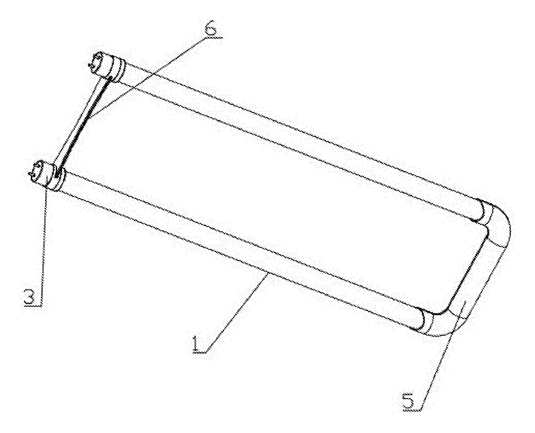
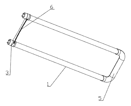
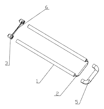
- The lamp uses two straight tubes (1) joined at the back by a rear support frame (5).
- The rear support frame consists of a first U-shaped piece (51) and a second U-shaped piece (52) that fit together.
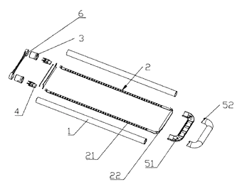
- The first U-shaped piece includes first installation parts (511) matching the ends of the straight tubes and a first connection part (512) linking them. At the joint between these parts sits a first positioning column (513).
- The LED light board (2) is formed as a single soft substrate. It has two light-emitting sections (21) running inside the straight tubes and a middle connecting section (22) joining them.
- During assembly, the middle connecting section bends around the first positioning column, which acts as a fixed turning point. This sets the bend radius and stops the substrate from over-bending and tearing.
- The second U-shaped piece (52) has a second positioning post (523) that sleeves over the first positioning column, locking the two frame halves together around the bend.
Who it is for
- Commercial lighting brands looking to expand their LED replacement catalog with U-shaped tubes for office troffers.
- Electrical wholesalers supplying contractors who retrofit older 2x4 fluorescent fixtures with LED U-lamps.
- Amazon sellers and e-commerce distributors focusing on direct-replacement LED tubes for facility maintenance buyers.
- Contract lighting manufacturers seeking a simpler internal structure to reduce assembly time and bill-of-materials costs.
How it works
The main parts
| No. | Part | What it does |
|---|---|---|
| 1 | Straight tubes | Glass tubes housing the light-emitting sections. |
| 2 | LED light board | One-piece soft substrate carrying the LEDs. |
| 21 | Light-emitting sections | The two straight segments of the board inside the tubes. |
| 22 | Middle connecting section | The flexible bridge between the two emitting sections. |
| 51 | First U-shaped piece | Main frame half holding the installation parts and positioning column. |
| 511 | First installation parts | Sections mating with the straight tube ends. |
| 512 | First connection part | Links the installation parts; carries ribs and hooks. |
| 513 | First positioning column | Vertical post guiding the bend of the middle section. |
| 514 | Positioning bosses | Horizontal guides spaced to match the board thickness. |
| 515 | First ribs | Spaced ridges pressing the board into place. |
| 517 | Hooks | Side latches on the first piece for joining the frame. |
| 52 | Second U-shaped piece | Covering frame half that mates with the first piece. |
| 523 | Second positioning post | Sleeves over the first positioning column. |
| 525 | Second ribs | Press against the middle connecting section. |
| 526 | Buckles | Snap onto the hooks to lock the two pieces together. |
Assembly steps
- Place the board: The light-emitting sections (21) are inserted into the straight tubes (1) and fixed to the inner walls with an adhesive.
- Route the bend: The middle connecting section (22) is laid horizontally and wrapped around the vertical first positioning column (513) on the first U-shaped piece (51).
- Align: The positioning bosses (514) on the first installation parts guide the edges of the soft substrate, keeping it centered.
- Close the frame: The second U-shaped piece (52) is placed over the first. Its second positioning post (523) slides down over the first positioning column (513).
- Snap shut: The buckles (526) on the second piece click onto the hooks (517) on the first piece, clamping the frame closed. The first ribs (515) and second ribs (525) press the middle connecting section flat.
Applications
Office ceiling troffers
Facility managers replacing T8 U-bend fluorescent tubes in 2x4 drop ceilings use these LED lamps. The soft substrate ensures the LEDs sit evenly inside the glass tubes, providing uniform light across desk surfaces without dark spots at the bend.
Retail store lighting
Shops using suspended U-tube fixtures benefit from the lower heat output compared to older fluorescents. Because the soft substrate manages heat without a heavy metal sink, the lamp remains lighter, reducing strain on ceiling mounts.
School classrooms
Maintenance teams in schools swap out flickering fluorescent U-tubes for steady LED versions. The snap-together rear support frame speeds up bulk replacements during short summer maintenance windows.
Hospital corridors
Healthcare facilities require reliable, glare-free lighting. The smooth bend guided by the positioning column prevents the micro-cracks that can occur in rigid boards, supporting longer service intervals in areas that run lights continuously.
Where it is less suitable
- Outdoor wet locations - the patent describes glass tubes and a molded frame, but does not specify IP-rated seals for exposed outdoor use.
- High-vibration industrial machinery - glass tubes may not withstand heavy vibration; polycarbonate alternatives would be needed.
- Decorative architectural fixtures - this is a functional replacement lamp designed for standard troffers, not custom shapes.
Frequently asked questions
Why use a soft substrate instead of a rigid board?
A soft substrate, such as a flexible printed circuit (FPC), bends easily around the tight radius at the base of the U-tube. The patent notes that it adapts better to the shape and eliminates the need to cut the board into segments or solder jumper wires across the bend.
How does the lamp handle heat without a metal heat sink?
The patent describes that the soft substrate itself provides better heat dissipation than a hard substrate in this configuration, spreading the thermal load along its surface. This removes the need to install a separate metal heat sink inside the tube, reducing parts and cost.
What stops the LED board from tearing when it bends?
The first U-shaped piece has a vertical positioning column at the corner. The middle connecting section of the soft substrate wraps around this column, which acts as a fulcrum. This controls the bend radius and prevents the substrate from folding too sharply and tearing.
How do the two frame pieces stay together?
The first U-shaped piece has hooks on both sides of its connection part, and the second U-shaped piece has matching buckles. When pressed together, the buckles snap onto the hooks. Additionally, a second positioning post on the second piece sleeves over the first positioning column to align the halves.
Are the straight tubes glass or plastic?
Claim 8 specifies that the straight tube is glass, and the light-emitting section is fixed to the inner wall with an adhesive. Claim 9 adds that the glass tube can be covered with a layer of heat-shrinkable light-transmitting film.
Can this use a rigid PCB instead of a soft one?
Yes. The patent description explicitly states that the LED light board can be either a flexible FPC board or a hard PCB board, depending on the manufacturer’s choice.
Does it fit standard U-bend fluorescent fixtures?
The patent covers the internal structure of the lamp—the tubes, substrate, and rear support frame. To fit standard North American fixtures, the appropriate bi-pin or quad-pin base must be integrated into the design during engineering.
Can this design be made and sold in the US?
The patent was filed only in China and has expired, so it does not restrict the design in the US or in China. However, the original assignee holds later US patents in this lighting field that cite this document—see Patent & Production—so we recommend a freedom-to-operate check before volume production.
Are you affiliated with the patent owner?
No. IP2M is an independent design and manufacturing service working from the public patent document.
Request a quote
Click Request a Quote below to see our email address - copy it, or open your email app with a ready-made message. Please mention patent CN205447315U in the subject.
Helpful details to include:
- Your company and channel (lighting brand, electrical wholesaler, Amazon seller, contract manufacturer)
- Target fixture type and required base (e.g., G13 bi-pin, 4-pin)
- Tube leg length (about 12 in. or 24 in., or custom)
- Wattage, lumens, and color temperature
- Substrate preference (soft FPC or hard PCB)
- Estimated quantity and target price
- Certification needs (UL, DLC, FCC)
- Timeline - when you would like samples and the first shipment
You can also reach us at (332) 203-9997.
Explore this product
Interested in building this?
Tell us your target market, quantity and timeline. We reply with options for prototyping, small-batch runs or volume production.
Send your inquiry to
Please put CN205447315U in the subject line and tell us your company, country, estimated quantity and timeline.
Prefer to talk? Call (332) 203-9997.
More product-ready patents
All Lighting patents →
Lighting
Wrist-Worn Flashlight with Click-Lock Angle Adjustment
Rechargeable wrist flashlight whose lamp turns and locks at an angle with a push button.
Patent CN113915544B
Lighting
Self-Folding Desk Lamp That Turns into a Phone Stand
Desk lamp with a shape-memory stem that unfolds when warm and folds into a phone stand.
Patent CN213237087U
Lighting
Ring-Shaped Outdoor Lantern That Lifts Off a Power-Bank Charging Base
Ring lantern with a battery handle that docks in a cone base with its own battery, clamp and charging plug.
Patent CN212408329U
Lighting
LED Flameless Candle with an Outside Flame Shade and Wax Dish Top
Battery LED candle: flame shade stands above a dished wax top, angled LEDs light a printed wick.
Patent CN205424561U
Lighting
Telescoping Tripod Portable Work Light with Fold-In Light Panels
Telescoping tripod work light with dual light panels that fold flat into the base.
Patent CN207298471U
Lighting
Self-Cooling and Self-Cleaning LED Street Light with Rainwater Harvesting
LED street lamp that harvests rain to cool its heat sink and spray-wash the lens automatically.
Patent CN205480639U
Browse by category
- Apparel & Accessories (22)
- Baby & Kids (16)
- Bags & Luggage (9)
- Bath & Personal Care (16)
- Car Accessories (10)
- Furniture, Bedding & Storage (12)
- Garden & Outdoor (18)
- Health & Wellness (8)
- Home, Kitchen & Cleaning (24)
- Lighting (12)
- Packaging & Containers (6)
- Pet Products (6)
- Phone & Camera Accessories (4)
- Retail Display (13)
- School, Office & Art (19)
- Sports & Recreation (25)
- Tools & Workshop (27)
- Toys & Games (12)
This page is based on the public patent document CN205447315U, assigned to Jiaxing Super Lighting Electric Appliance Co Ltd. IP2M is an independent manufacturing service and is not affiliated with, endorsed by or licensed by the patent owner. Images marked as concept renderings are illustrations, not photos of an existing product. Patent status information is provided for reference only and is not legal advice; confirm freedom to operate for your market before production. Full disclaimer.