
Patent CN205487209U
Updated October 25, 2026Magnetically Repositionable LED Advertising Panel
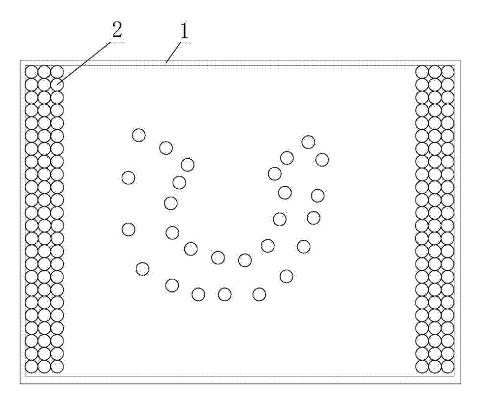
Fixed LED signs force you to choose one message or buy a whole new board. This panel lets operators rearrange individual lamp beads inside the housing to spell out different words, logos or patterns whenever the campaign changes. Each LED module has a ferromagnetic base. By pressing an external electromagnet against the bottom reflector, the operator pulls the base down, compresses the return spring, slides the LED to a new coordinate, and switches off the magnet. The spring pushes the module back up so its top leaf spring and bottom spring regain contact with the conductive films that supply power. No need to open the housing.
- China utility model - lapsed
- No filings outside China
- Signage & retail display
- Electromagnetically repositionable LEDs
Splat! What let you down?
🧲
Magnetic repositioning
An external electromagnet placed against the bottom reflector pulls each LED module downward so it can be slid to a new spot.
💡
Spring-loaded contacts
A return spring below and a leaf spring above keep the lamp bead pressed against the conductive films for power.
🛡️
Closed enclosure
The upper transparent plate and bottom reflector stay closed; LEDs move inside without disassembly.
🔄
Changeable graphics
Rearrange multiple lamp beads to spell new text or draw new shapes as the advertising campaign changes.
Bring this product to market
- ✓ Patent vetted China-only family and legal status checked
- 2 Product brief · now How it works, uses and options written up
- 3 Prototype First samples for buyers to review
- 4 Pilot run Small first batch for launch customers
- 5 Volume production Repeat orders at scale
Buyer interest
– of 100 buyers needed to start prototyping
One click, no sign-up. Each vote is one real visitor, and products with the most interest go to prototyping first.
Build team: no members yet. Need a partner, co-funding or skills to build this? Join and we introduce the team once it forms.
The problem
Retail stores, event venues and public spaces often rely on fixed-layout LED signs. When the promotional message needs to change, the business either swaps the entire board or uses a fully programmable pixel matrix, both of which add cost and complexity. Simple static boards cannot adapt to seasonal campaigns, daily specials or rotating sponsor logos without physical replacement. According to the patent, the goal is an advertising panel whose display pattern can be adjusted to specific needs without dismantling the shell, making it convenient to regulate the position of each LED lamp bead.
The solution
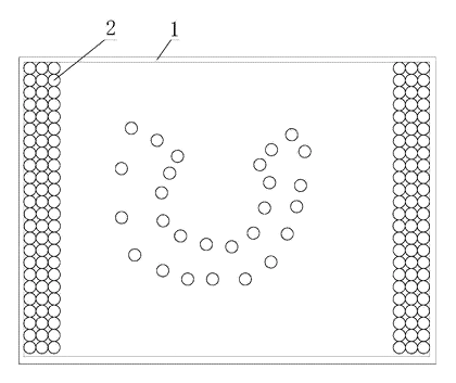
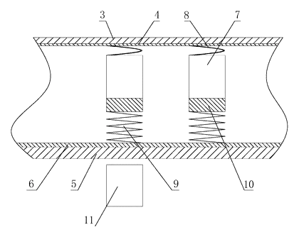
- The shell (1) consists of an upper transparent plate (3) and a bottom reflector (5). Multiple LEDs (2) are arranged between them.
- A transparent conductive film (4) coats the inner surface of the upper plate, and a reflective conductive film (6) coats the inner surface of the bottom plate. These two films supply positive and negative voltage respectively.
- Each LED includes a lamp bead (7), a ferromagnetic base (10), a return spring (9) and a leaf spring (8). The lower end of the lamp bead is fixed to the top of the ferromagnetic base.
- The leaf spring sits at the upper end of the lamp bead and presses upward against the transparent conductive film. The return spring is fixed to the underside of the ferromagnetic base and presses downward against the reflective conductive film.
- To move an LED, an electromagnet (11) is placed on the outside of the bottom reflector. It attracts the ferromagnetic base, compressing the return spring so the module drops slightly and can be dragged across the panel.
- When the electromagnet is switched off, the return spring pushes the module back up, restoring electrical contact through both springs.
Who it is for
- Independent retail shops that rotate window promotions weekly and want a physical illuminated sign they can update themselves without buying new hardware each time.
- Event rental companies supplying signage for trade shows, conferences and pop-up markets where every client needs a different logo or directional text.
- Educational institutions and makerspaces looking for a hands-on display technology demonstrator that shows how magnetic actuation and conductive films interact.
- Menu board operators in cafes or food courts that change item highlights daily but prefer large, bright physical indicators over small pixel screens.
How it works
The main parts
| No. | Part | What it does |
|---|---|---|
| 1 | Shell | Encloses the components; made of the upper plate and bottom reflector. |
| 2 | LED | The complete light-emitting module that moves within the shell. |
| 3 | Upper transparent plate | Lets light out while supporting the transparent conductive film. |
| 4 | Transparent conductive film | Coated on the inner side of the upper plate; carries one voltage polarity. |
| 5 | Bottom reflector | Forms the back of the shell and reflects light forward. |
| 6 | Reflective conductive film | Coated on the inner side of the bottom reflector; carries the opposite voltage polarity. |
| 7 | Lamp bead | The actual light-emitting diode element. |
| 8 | Leaf spring | Mounted at the top of the lamp bead; slides against the transparent conductive film to maintain electrical contact. |
| 9 | Return spring | Fixed below the ferromagnetic base; pushes the module upward and contacts the reflective conductive film. A conduction disk may be installed at its lower end. |
| 10 | Ferromagnetic base | Frustum cone structure matching the diameter of the lamp bead; attracted by the electromagnet. |
| 11 | Electromagnet | Placed outside the bottom reflector to pull the ferromagnetic base down during repositioning. Its diameter matches the base. |
Repositioning steps
- Activate the electromagnet - place the electromagnet (11) against the outside of the bottom reflector (5) near the target LED and switch it on.
- Compress the spring - the magnetic field attracts the ferromagnetic base (10), pulling the entire LED module (2) downward and compressing the return spring (9). This breaks or loosens the pressure of the leaf spring (8) against the transparent conductive film (4).
- Slide the module - move the electromagnet along the outside of the bottom reflector. Because the magnet holds the base, the LED drags across the interior space to the desired coordinate.
- Release - switch off the electromagnet. The elastic force of the return spring pushes the ferromagnetic base back up.
- Re-establish contact - the leaf spring at the top of the lamp bead presses firmly against the transparent conductive film again, and the return spring (or its conduction disk) presses against the reflective conductive film, completing the circuit so the lamp bead lights up in its new position.
- Repeat - perform the same steps for each remaining LED to build the full graphic or text pattern.
Applications
Retail storefront windows
Shop owners arrange the lamp beads to spell out weekend sale prices or seasonal greetings. When the promotion ends, they use the electromagnet to drag the beads into a new word without replacing the board or dealing with fragile wiring.
Trade show booths
Exhibitors rent booth space for short events and need their company name lit up quickly. The rental provider sets the beads before shipping, and if the exhibitor wants to highlight a different product line on day two, the on-site staff repositions the modules in minutes.
University engineering labs
Instructors use the panel to demonstrate how transparent conductive coatings deliver power to moving contacts. Students practice mapping coordinates and operating the electromagnet, turning a theoretical lesson on circuits and magnetism into a visible result.
Hospitality wayfinding
Hotels and conference centers mount these panels near elevators to point guests toward specific banquet rooms. As the daily schedule changes, the facilities team slides the LEDs to form new arrows or room numbers rather than printing paper signs.
Cafe daily specials
A cafe highlights its “soup of the day” by arranging a few bright beads around the menu item’s printed card behind the transparent plate. The visual emphasis shifts as the kitchen rotates dishes, keeping the physical menu board dynamic.
Where it is less suitable
- High-resolution video or scrolling text - this design moves discrete lamp beads manually, so it cannot replicate the thousands of pixels needed for video playback or rapid scrolling messages.
- Outdoor weather exposure - the patent describes a shell, but the sliding mechanism relies on spring contact against conductive films, which may degrade under extreme temperature swings or heavy condensation unless specifically ruggedized.
- Fully automated remote updates - because an operator must physically hold the electromagnet against the panel to move each bead, it does not support software-driven content scheduling from a central server.
Frequently asked questions
How do the LEDs move without opening the panel?
Each lamp bead is mounted on a ferromagnetic base inside the shell. When you place the external electromagnet against the outside of the bottom reflector, it pulls the magnetic base downward, compressing the return spring. You then slide the magnet along the exterior, dragging the LED to a new spot. Turning off the magnet lets the spring push the module back up into contact with the conductive films.
How does the LED receive power after it is repositioned?
The inner surface of the upper transparent plate is coated with a transparent conductive film, and the inner surface of the bottom reflector has a reflective conductive film. A leaf spring at the top of the lamp bead presses against the upper film, and the return spring (or a conduction disk at its base) presses against the lower film. These two films carry the positive and negative voltages, so the LED stays powered wherever it stops.
Will dragging the LEDs scratch the conductive film?
The patent specifies spring contacts rather than rigid pins. In production, the leaf spring and the conduction disk must be designed with smooth, rounded contact surfaces and appropriate spring force to glide across the film without gouging it. Film hardness and spring material are confirmed on prototypes during development.
Do I need a separate electromagnet for each LED?
You use one electromagnet at a time. The operator positions one LED, releases it, and moves on to the next. The patent notes that the diameter of the electromagnet matches the diameter of the ferromagnetic base.
What shape is the magnetic base?
The patent describes the ferromagnetic base as a frustum cone structure, meaning it tapers slightly like a truncated cone. Its diameter matches the lamp bead.
Can the panel display complex images or just simple letters?
The resolution depends entirely on how many LED modules are placed inside the shell. Because each bead is moved individually by hand, the system is best suited for simple text, logos, arrows or geometric shapes rather than high-density photographic images.
Can this design be made and sold in the US?
The patent was filed only in China and has lapsed due to non-payment of annual fees, so it does not restrict the design in the US or in China. Magnetically manipulated displays may be covered by other US patents - see Patent & Production - so we recommend a freedom-to-operate check before volume production.
Are you affiliated with the patent owner?
No. IP2M is an independent design and manufacturing service working from the public patent document.
Request a quote
Click Request a Quote below to see our email address - copy it, or open your email app with a ready-made message. Please mention patent CN205487209U in the subject.
Helpful details to include:
- Your company and channel (signage brand, retail fixture supplier, event rental company, educational equipment distributor)
- Panel dimensions and approximate number of LEDs
- Mounting method (wall, window, freestanding)
- Power requirements and plug type
- Estimated quantity and target price
- Timeline - when you would like samples and the first shipment
You can also reach us at (332) 203-9997.
Explore this product
Interested in building this?
Tell us your target market, quantity and timeline. We reply with options for prototyping, small-batch runs or volume production.
Send your inquiry to
Please put CN205487209U in the subject line and tell us your company, country, estimated quantity and timeline.
Prefer to talk? Call (332) 203-9997.
More product-ready patents
All Retail Display patents →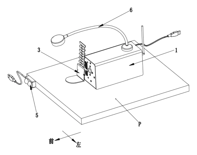
Retail Display
Motorized Shelf Display That Presents a Product to Shoppers
Shelf unit that lifts a product over the price rail toward shoppers when a sensor detects them.
Patent CN215077184U
Retail Display
Portable Advertising Light Box with Spinning LED Display
Portable ad box whose spinning LED bars draw images and text; content changes by wireless or USB.
Patent CN207425291U
Retail Display
Automated Folding Store Shelf That Pushes Products Up to the Customer
Double-sided shelf for unmanned stores: folding tiers, screw pushers and lift cylinders present stock.
Patent CN109645754B
Retail Display
Motorized Rotating Display Pedestal with Lift Column, Info Screen and Clip-On Display Racks
Mobile pedestal: motorized rotating cube with lit faces and racks, electric lift column and info screen.
Patent CN208875862U
Retail Display
Thin Outdoor LED Video Wall Cabinet with Magnetic Modules and Tool-Free Locks
Thin outdoor LED wall cabinet: magnetic modules and rear body, rotary locks, finned rear cooling.
Patent CN205354557U
Store & Display
Mist-Cooled Produce Display Rack with Integrated Humidifier
Three-tier produce rack piping ultrasonic mist over each shelf to humidify fruits and vegetables.
Patent CN213640365U
Browse by category
- Apparel & Accessories (22)
- Baby & Kids (16)
- Bags & Luggage (9)
- Bath & Personal Care (16)
- Car Accessories (10)
- Furniture, Bedding & Storage (12)
- Garden & Outdoor (18)
- Health & Wellness (8)
- Home, Kitchen & Cleaning (24)
- Lighting (12)
- Packaging & Containers (6)
- Pet Products (6)
- Phone & Camera Accessories (4)
- Retail Display (13)
- School, Office & Art (19)
- Sports & Recreation (25)
- Tools & Workshop (27)
- Toys & Games (12)
This page is based on the public patent document CN205487209U, assigned to Xingtai Polytechnic College. IP2M is an independent manufacturing service and is not affiliated with, endorsed by or licensed by the patent owner. Images marked as concept renderings are illustrations, not photos of an existing product. Patent status information is provided for reference only and is not legal advice; confirm freedom to operate for your market before production. Full disclaimer.