At a glance
| Patent number | CN205625287U (application CN201620149050) |
| Type | China utility model (实用新型) - protects product shape and structure |
| Original title | Folding chair and its support (折叠椅及其支架) |
| Patent owner | Individual |
| Inventors | Chen Wei |
| Filing date | 2016-02-26 |
| Grant date | 2016-10-12 |
| Status (China) | Expired - a China utility model lasts at most 10 years from filing; the term ended on 2026-02-26 |
| Patent family | Chinese filings only - no US, European, Japanese, PCT or other filings listed |
| Cited by | 2 later documents |
| Source | Google Patents (search for CN205625287U) |
What the claims cover, in plain language
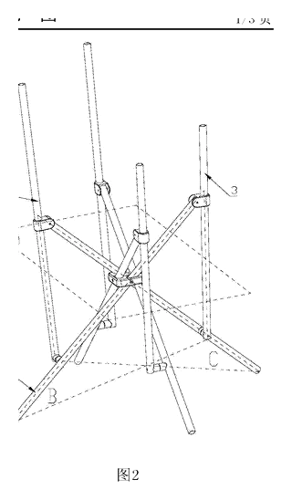
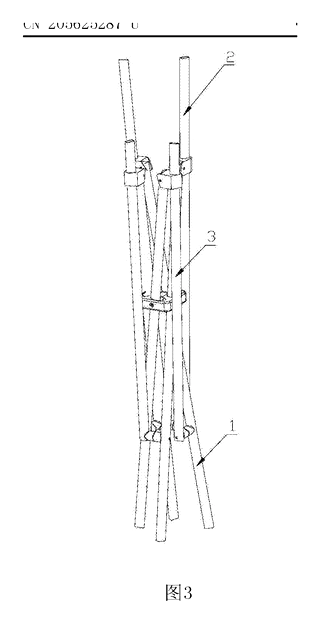
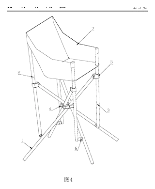
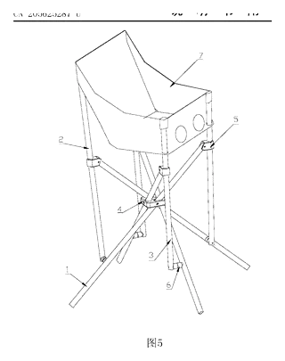
Claim 1 - defines a folding chair support comprising a fixed seat, base poles, backrest poles, armrest poles, and sliding parts. The key feature is the connection logic: the base poles are hinged to the seat, while the tops of the base poles are hinged to sliding parts that travel along the backrest or armrest poles. Specifically, the sliding parts on one side connect to the base poles on the opposite side.
Claim 2 - specifies the count: 4 base poles (2 front, 2 rear), 2 backrest poles, 2 armrest poles, and 4 sliding parts. It details the specific pairing: e.g., an armrest slider connects to the top of the rear base pole on the opposite side.
Claim 4 - describes the sliding part itself: a sleeve with two ears that hinge to the base pole top, allowing rotation while sliding linearly along the vertical pole.
Claim 8 - extends protection to the complete folding chair, including the cushion attached to the tops of the armrest and backrest poles.
This is a simplified reading for orientation only. The legal scope is defined by the exact claim wording in the official Chinese document.
What this means for US production
This patent was filed only in China and has expired, so it no longer restricts anyone in China either. It has no US or other foreign counterpart.
Two points to settle early:
- Other patents may exist. Folding chair mechanisms are a crowded field with many existing US patents covering various scissor, cantilever, and sliding geometries. A freedom-to-operate (FTO) review is essential to ensure this specific cross-linked slider arrangement does not infringe on active US patents held by major outdoor or furniture manufacturers.
- Safety Standards. Furniture sold in the US must meet strict stability and strength standards regardless of patent status.
Customization and manufacturing
What can be customized
| Area | Options |
|---|---|
| Tube Material | Steel (powder coated), Aluminum (anodized), or Wood/MDF for aesthetic blends |
| Slider Design | Plastic injection molded sleeves vs. machined metal bushings |
| Cushion Fabric | Canvas, Oxford cloth, Mesh, or Leatherette; varying foam densities |
| Dimensions | Seat height, backrest angle, and folded thickness can be adjusted by changing pole lengths |
| Finish | Matte black, white, silver, or custom brand colors |
Things to plan for (US market)
- ASTM F1938 - Standard Specification for Performance Requirements for Portable Folding Chairs. This covers durability, fatigue, and stability tests.
- CPSC Guidelines - General consumer product safety rules apply, particularly regarding pinch points in the sliding mechanism and sharp edges on folded components.
- Proposition 65 - If using certain plastics or coatings, California warning labels may be required.
How a project runs
- Inquiry - Define target dimensions, weight capacity, and material preferences.
- Design - CAD modeling of the slider-pole interaction to ensure smooth folding without binding.
- Prototype - Build sample frames using bent/welded tubes and 3D-printed or machined sliders.
- Pilot Run - Conduct ASTM F1938 cycle testing and load validation.
- Production - Tube bending, welding, powder coating, slider molding, and final assembly.
Quantities & timeline
Tooling for plastic sliders requires injection molds. Metal frames rely on tube bending dies and welding jigs. Powder coating lines handle finishing. Development typically takes 8-12 weeks for validated prototypes before mass production tooling begins. Send us your target dimensions, material choice, estimated quantity, and budget range and we will reply with options.
Production notes
Tooling and process
Likely processes include steel tube bending and welding for the frame, followed by powder coating. Injection molding is typically used for the sliding parts. Wood or MDF machining might be added for decorative elements.
Cost drivers
Costs typically depend heavily on tube diameter and wall thickness, which affect material usage. The connector and bracket count drives assembly labor. Surface finish quality also impacts cost.
Prototyping path
Typically, prototyping starts with a 3D model and load path check. Create a welded or bolted frame sample. Use 3D-printed connectors for initial slider fitting. Perform load test on the frame before finalizing tooling.
What we would change before tooling
We would likely adjust the slider ear geometry to prevent tipping under uneven load. Wall thickness and joint design should be verified to avoid loose joints after repeated load.
Common failure points
Common issues typically include stripped screws in particle board if wood parts are used, or hinge boss and pivot wear in the sliding mechanism. Coating chips at edges are also frequent if handling is rough.
Patent drawings
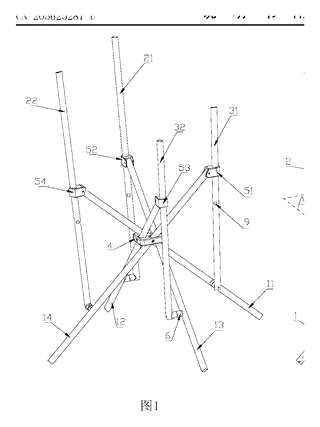
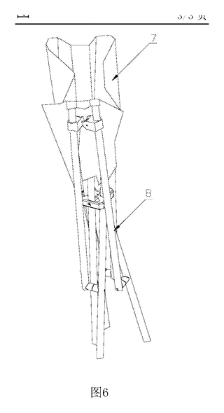
Drawings reproduced from the public patent document for reference.