
Patent CN205765859U
Updated October 27, 2026Multifunctional Screwdriver with a Sliding Bit Changer and Locking Plate
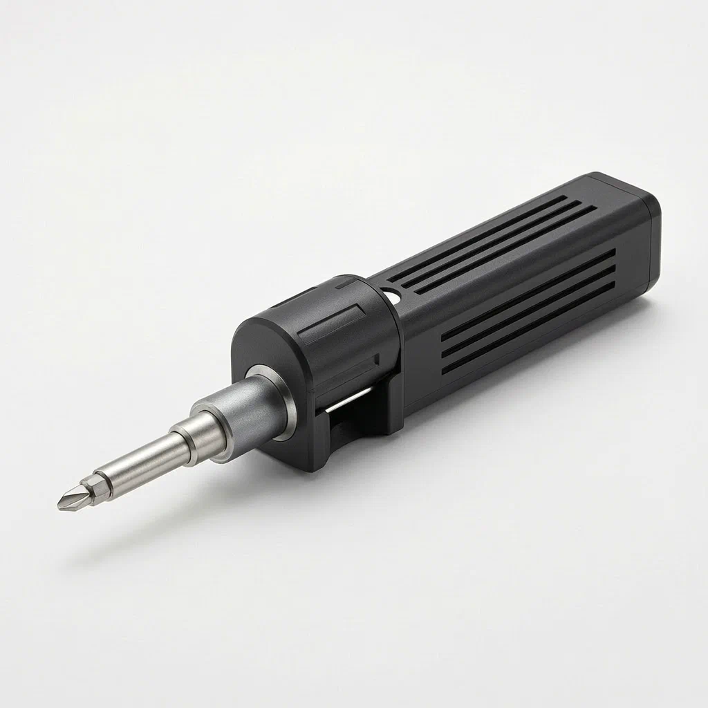
Standard multi-bit screwdrivers require users to manually pull out one bit and insert another, often dropping small pieces or struggling with tight chucks. This design automates the change. A rotating turret on the front handle holds multiple driver bits. When you slide the front handle forward against the rear handle, an internal push rod passes through the turret and pushes the selected bit directly into the working position. An elastic locking plate snaps into a cone groove on the push rod to hold everything firmly in place during use. To take the tool apart for cleaning or repair, align the inner and outer handle holes and press the locking plate with a tool so it elastically deforms and releases the two halves.
- China utility model - lapsed
- No filings outside China
- Hand tools & workshop equipment
- Plastic handles, metal push rod, elastic locking plate
Splat! What let you down?
🔄
Rotating bit turret
A runner on the pull end holds driver bits of different models and rotates to select the needed one.
➡️
Slide-to-deploy mechanism
Sliding the pull end relative to the rear lug drives a push rod through the turret to push the bit forward.
🔒
Elastic locking plate
An elastic collet at the pull end's back engages a cone groove on the push rod to limit sliding distance.
🔧
Tool-assisted disassembly
Aligned inner and outer handle holes allow a tool to deform the locking plate and separate the handles.
Bring this product to market
- ✓ Patent vetted China-only family and legal status checked
- 2 Product brief · now How it works, uses and options written up
- 3 Prototype First samples for buyers to review
- 4 Pilot run Small first batch for launch customers
- 5 Volume production Repeat orders at scale
Buyer interest
– of 100 buyers needed to start prototyping
One click, no sign-up. Each vote is one real visitor, and products with the most interest go to prototyping first.
Build team: no members yet. Need a partner, co-funding or skills to build this? Join and we introduce the team once it forms.
The problem
Multi-bit screwdrivers are common in workshops and homes, but changing the bit usually involves pulling one out by hand and pushing another in. Small bits are easy to drop, especially when working overhead or in dim light. Manual chucks can wear out or jam, making swaps slow. Furthermore, many multi-bit tools are difficult to open for internal cleaning if dust or debris gets inside the storage chamber. A mechanism is needed that advances the bit automatically when the handles move together, holds it securely during driving, and allows the user to separate the tool halves without specialized factory equipment.
The solution
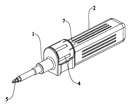
- The screwdriver has two main body sections: a pull end (1) and a rear lug (2), with the pull end slidably socketed over the rear lug.
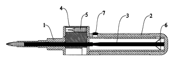
- A push rod (3) is fixed inside the rear lug and extends forward.
- A runner (4), acting as a rotating turret, is mounted on the pull end. It holds driver bits (5) of different models around its circumference.
- When the user slides the pull end toward the rear lug, the push rod passes sequentially through the runner, contacting the selected driver bit and pushing it out to the operating position.
- A locking plate (6), formed as an elastic collet, sits at the inner back end of the pull end and extends toward the push rod.
- The push rod features a locked groove (31), shaped as a cone groove along its circumference. The locking plate snaps into this groove to limit the sliding distance between the pull end and the rear lug, keeping the bit extended and locked.
- For disassembly, the pull end has an inner handle hole (11) and the rear lug has an outer handle hole (21). When the locking plate is seated in the groove, these holes align. Inserting a tool through them causes the locking plate to elastically deform, unlocking it from the groove so the pull end and rear lug can be pulled apart. A folding block (7) covers the outer handle hole.
Who it is for
- Hand tool brands looking for a multi-bit screwdriver with a mechanical deployment action rather than a manual chuck.
- Amazon private-label sellers needing a distinct, demonstrable feature—sliding the handle to pop out the bit—for product videos and listings.
- Wholesalers supplying hardware stores who want a compact all-in-one driver that reduces loose bits lost by retail customers.
- Promotional product companies sourcing branded tools where the folding block and handle shape offer visible areas for logo printing.
How it works
The main parts
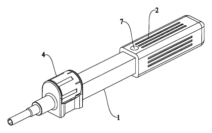
| No. | Part | What it does |
|---|---|---|
| 1 | Pull end | Front handle section that slides over the rear lug; holds the runner. |
| 2 | Rear lug | Rear handle section; anchors the push rod. |
| 3 | Push rod | Fixed rod that passes through the runner to push the selected bit forward. |
| 4 | Runner | Rotating turret holding driver bits of different models. |
| 5 | Driver bits | Interchangeable tips stored in the runner. |
| 6 | Locking plate | Elastic collet at the inner back end of the pull end. |
| 11 | Inner handle hole | Hole in the pull end penetrating to the locking plate. |
| 21 | Outer handle hole | Hole in the rear lug that aligns with the inner handle hole. |
| 31 | Locked groove | Cone groove on the push rod circumference engaged by the locking plate. |
| 7 | Folding block | Cover provided on the outer handle hole. |
Operating steps
- Select the bit - rotate the runner on the pull end until the desired driver bit aligns with the push rod.
- Deploy the bit - push the pull end toward the rear lug. The push rod slides through the runner and forces the selected bit out to the operating position.
- Lock - the elastic locking plate snaps into the cone groove on the push rod, stopping further travel and securing the bit.
- Drive screws - use the tool normally; the locked groove prevents the handles from separating under pressure.
- Disassemble - fold back the block to expose the outer handle hole. Insert a tool through the aligned outer and inner handle holes to press the locking plate. The elastic deformation releases the plate from the groove, allowing the pull end to slide off the rear lug for cleaning or bit replacement.
Applications
Home repair kits
Homeowners keep one tool instead of a set of individual screwdrivers. The rotating runner stores multiple bit models, and the slide action deploys the right one without searching through a case.
Electronics assembly benches
Technicians frequently switch between Phillips, slotted, and Torx sizes. Pushing the handle forward seats the new bit instantly, saving time during repetitive board-level work.
Field service technicians
Appliance and HVAC repair workers carry heavy bags. A single sliding-handle screwdriver replaces several fixed drivers, and the folding block keeps the disassembly hole sealed against job-site dust.
Retail blister packs
The distinct mechanical action—sliding the handle to extend the bit—is easy to demonstrate on packaging graphics. Tool buyers understand the function immediately without reading instructions.
Where it is less suitable
- Heavy-duty construction framing - the sliding plastic body and internal push rod are designed for general fastening, not high-torque structural lag bolts.
- Insulated electrical work - the patent does not describe dielectric materials or VDE ratings required for live circuits.
- Precision watchmaking - the bits and runner are sized for standard hardware, not microscopic horology screws.
Frequently asked questions
How does the bit change work?
You rotate the runner on the front handle to line up the bit you need. Then you slide the front handle toward the rear handle. The internal push rod passes through the runner and pushes that specific bit out to the working position.
How is the bit held in place while driving screws?
An elastic locking plate at the back of the front handle snaps into a cone groove on the push rod. This limits the sliding distance and locks the two handle sections together so the bit stays extended under torque.
How do I take the screwdriver apart?
Fold back the block on the rear handle to reveal the outer handle hole. Insert a small tool through the outer hole and the aligned inner hole on the front handle. Pressing inward causes the elastic locking plate to deform and release from the groove, letting you pull the two halves apart.
What size bits does it take?
The patent describes storing driver bits of different models in the runner but does not specify the shank diameter. Standard sizes such as 1/4-inch hex or 4 mm precision shanks are set in design and confirmed on prototypes.
How many bits fit in the runner?
The exact number of slots is not stated in the patent. The runner capacity depends on its diameter and the bit size, to be confirmed in design.
Can the handle material be changed?
Yes. The patent focuses on the mechanical structure. The pull end and rear lug can be molded from various plastics or fitted with soft-grip overmolds depending on the target market.
Can this design be made and sold in the US?
The patent was filed only in China and is lapsed, so it does not restrict the design in the US or in China. Multi-bit screwdrivers may be covered by other US patents - see Patent & Production - so we recommend a freedom-to-operate check before volume production.
Are you affiliated with the patent owner?
No. IP2M is an independent design and manufacturing service working from the public patent document.
Request a quote
Click Request a Quote below to see our email address - copy it, or open your email app with a ready-made message. Please mention patent CN205765859U in the subject.
Helpful details to include:
- Your company and channel (hand tool brand, Amazon seller, wholesaler, promotional supplier)
- Number of bits and shank size (e.g., 1/4-inch hex, 4 mm)
- Handle material and grip preferences
- Colors and branding requirements
- Estimated quantity and target price
- Timeline - when you would like samples and the first shipment
You can also reach us at (332) 203-9997.
Explore this product
Interested in building this?
Tell us your target market, quantity and timeline. We reply with options for prototyping, small-batch runs or volume production.
Send your inquiry to
Please put CN205765859U in the subject line and tell us your company, country, estimated quantity and timeline.
Prefer to talk? Call (332) 203-9997.
More product-ready patents
All Tools & Workshop patents →
Tools & Workshop
Rolling Tool Box with Telescoping Step Ladder
Telescoping A-frame ladder with an attached rolling tool box that slides to your working height.
Patent CN206290197U
Tools & Workshop
Folding 3-Handle Wrench Multi-Tool
Folding three-handle wrench multi-tool with magnetic screwdriver bits, saw, file and bottle opener.
Patent CN205290875U
Tools & Workshop
Rolling Auto-Repair Tool Cabinet with Built-In Lights
Lockable rolling tool cabinet for car repair with interior lights, a lubricant tray, parts drawers and a tool bay.
Patent CN205989314U
Tools & Workshop
Wide-Opening Folding Bolt Cutter
Bolt cutter with linked, gear-meshing handles that open up to 190° and fold in half for storage.
Patent CN207206226U
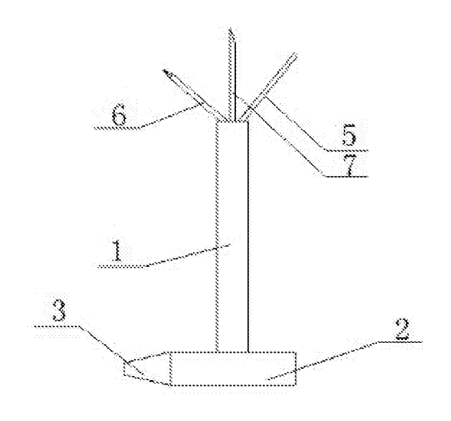
Tools & Workshop
Nail-Holding Hammer with Fold-Out Drivers
Hammer with a nail-holding T-slot in the head and fold-out drivers stored in the handle.
Patent CN205254927U
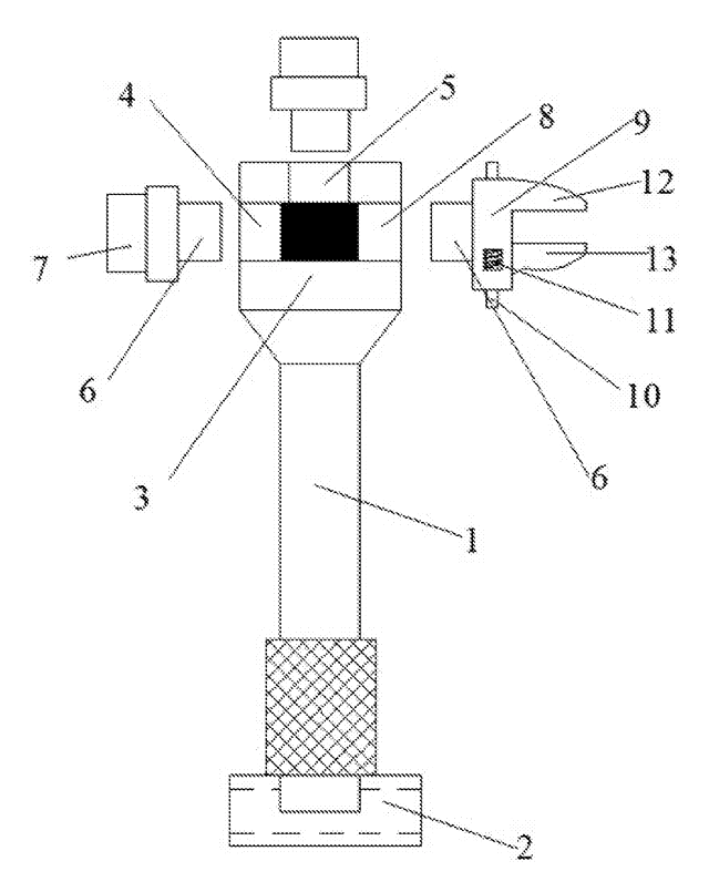
Tools & Workshop
Modular Wrench with Screw-On Heads
Wrench handle with a three-way threaded hub for screw-on adjustable and hex heads, plus a pipe sleeve.
Patent CN206216564U
Browse by category
- Apparel & Accessories (22)
- Baby & Kids (16)
- Bags & Luggage (9)
- Bath & Personal Care (16)
- Car Accessories (10)
- Furniture, Bedding & Storage (12)
- Garden & Outdoor (18)
- Health & Wellness (8)
- Home, Kitchen & Cleaning (24)
- Lighting (12)
- Packaging & Containers (6)
- Pet Products (6)
- Phone & Camera Accessories (4)
- Retail Display (13)
- School, Office & Art (19)
- Sports & Recreation (25)
- Tools & Workshop (27)
- Toys & Games (12)
This page is based on the public patent document CN205765859U, assigned to NINGBO RUIXIANG PLASTICS Co Ltd. IP2M is an independent manufacturing service and is not affiliated with, endorsed by or licensed by the patent owner. Images marked as concept renderings are illustrations, not photos of an existing product. Patent status information is provided for reference only and is not legal advice; confirm freedom to operate for your market before production. Full disclaimer.