At a glance
| Patent number | CN205765859U (application CN201620525110) |
| Type | China utility model (实用新型) - protects product shape and structure |
| Original title | A kind of convenient multifunctional screw driver of assembly and disassembly (一种组装拆卸方便的多功能螺丝刀) |
| Patent owner | NINGBO RUIXIANG PLASTICS Co Ltd |
| Inventors | Mao Dongchao, Luo Jiajie |
| Filing date | 2016-05-27 |
| Grant date | 2016-12-07 |
| Status (China) | Lapsed - terminated for non-payment of annual fees (recorded 2018-06-15) |
| Patent family | Chinese filings only - no US, European, Japanese, PCT or other filings listed |
| Cited by | 3 later documents |
| Source | Google Patents (search for CN205765859U) |
What the claims cover, in plain language
Claim 1 - a multifunctional screwdriver with a pull end slidably socketed onto a rear lug. A push rod is fixed inside the rear lug. A runner is rotationally connected to the pull end and holds driver bits of different models. Sliding the pull end relative to the rear lug causes the push rod to pass through the runner and push a selected bit to the operating position. A locking plate is arranged at the inner back end of the pull end and extends to the push rod. The push rod has a locked groove that coordinates with the locking plate to limit the sliding distance between the pull end and the rear lug.
Claim 2 - the locking plate is an elastic collet. The pull end has an inner handle hole penetrating to the locking plate, and the rear lug has an outer handle hole. When the locking plate sits in the locked groove, the two holes align. A tool inserted through the holes causes the locking plate to elastically deform, releasing it from the groove so the pull end and rear lug can be separated. Claim 3 - the outer handle hole is provided with a folding block. Claim 4 - the locked groove is a cone groove opened along the circumference of the push rod.
This is a simplified reading for orientation only. The legal scope is defined by the exact claim wording in the official Chinese document.
What this means for US production
This patent was filed only in China and is lapsed, so it no longer restricts anyone in China either. It has no US or other foreign counterpart.
Before tooling, check these two items:
- Other patents may exist. Wheelfoat, Inc. (also recorded as Wheelfloat, Inc.) holds later patents in related tool fields (WO2020060697A1, US11148276B2, US11654534B2) that cite this document. Multi-bit screwdrivers and quick-change tool handles are heavily patented by major hand-tool manufacturers, so a freedom-to-operate (FTO) review of the sliding deployment and collet-lock mechanism is needed before tooling.
- Bit retention force. The depth of the cone groove and the spring rate of the elastic collet determine how much torque the tool can transmit before the handle slips; these dimensions must be confirmed on prototypes.
Customization and manufacturing
What can be customized
| Area | Options |
|---|---|
| Handle material | ABS, PP, TPR overmold for grip |
| Runner capacity | Number of bit slots to be confirmed in design |
| Bit types | Phillips, slotted, Torx, hex; standard 1/4-inch or 4 mm shanks |
| Push rod length | Set in design to match overall handle travel |
| Colors | Custom handle and runner colors for branding |
| Folding block | Shape and hinge style of the outer hole cover |
Things to plan for (US market)
- California Proposition 65 - plastic resins, colorants and metal plating must be screened for listed chemicals.
- CPSC regulations - if marketed for children’s educational or toy use, ASTM F963 applies; for general adult hand tools, standard consumer product safety rules apply.
- Labeling - country of origin marking is required by US Customs.
How a project runs
- Inquiry - target market, bit count, handle material and quantity.
- Design - CAD models covering the pull end, rear lug, runner, push rod and locking plate geometry.
- Prototype - Printed or machined handles that let you check the sliding action, bit deployment and elastic release.
- Pilot run - injection molding of handles and runner, machining of push rods, assembly and torque testing.
- Production - full-scale molding, metal stamping or turning, assembly, quality inspection and packing.
Quantities & timeline
The pull end, rear lug and runner require injection molds. The push rod needs turning or stamping dies, and the locking plate requires precise forming to achieve the correct elastic deformation. Cycle times depend on mold cavitation. Send us your bit count, handle material, color requirements, estimated quantity and target price and we will reply with options.
Patent drawings
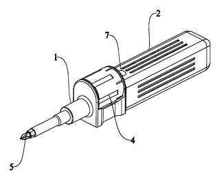
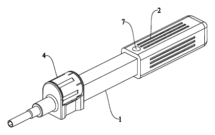
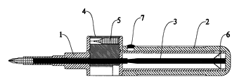
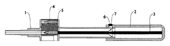
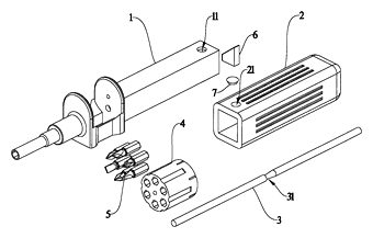
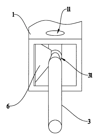
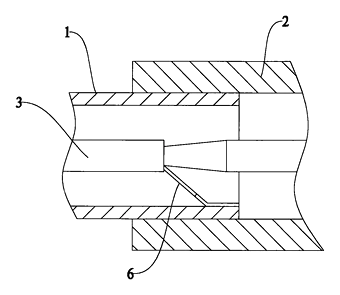
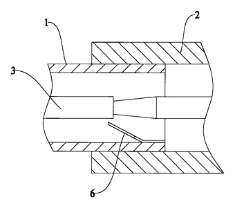
Drawings reproduced from the public patent document for reference.