
Patent CN205876899U
Updated October 26, 2026Composite Furniture Stable Structure with Connecting Plate and U-Clamp
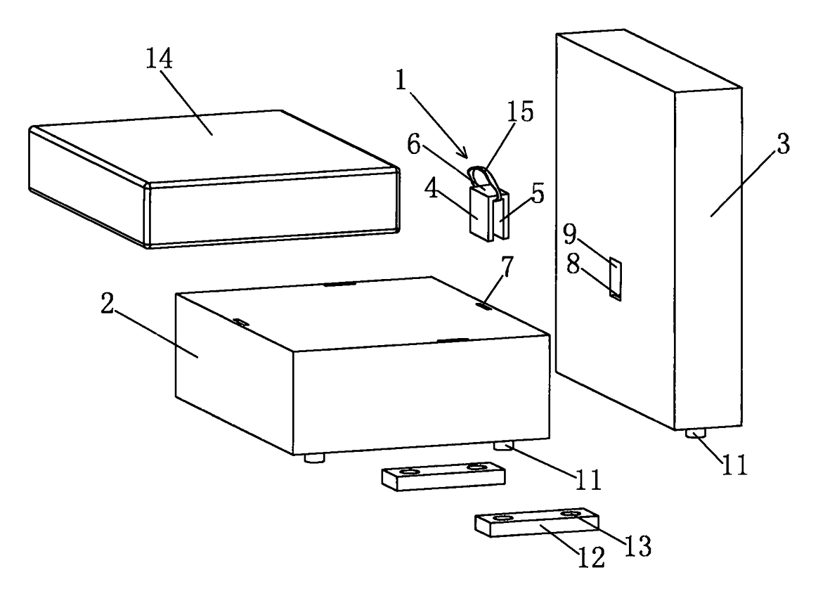
Modular furniture often wobbles where separate sections meet, because the joints rely only on bolts that loosen over time or require tools during setup. This composite furniture structure solves that issue by tying the modules together at both the floor and the top. At the bottom, a connecting plate spans the junction between a first support member and a second support member. The legs of each module drop into positioning holes on this plate, and tapered guide mouths help them slide in without forcing. The height of the connecting plate matches the height of the legs, keeping the base flush. At the top, a U-clamp connects the two members: its first foot and second foot insert into matching slots on the support members, locking them together. One module can act as a seat portion while the other serves as another seat, a backrest, or an armrest part. Because the pieces align through the plate and clamp together at the top, the finished unit stands steady without complex hardware.
- China utility model - expired
- No filings outside China
- Furniture & bedding
- Connecting plate, positioning holes, U-clamp connector
Splat! What let you down?
🔗
Bottom connecting plate
A plate spans the junction of two support members, with positioning holes that receive the legs directly.
📐
Tapered guide mouths
The upper ends of the positioning holes are tapered, guiding the legs into place during assembly.
🛠️
Top U-clamp connector
A U-clamp with two feet inserts into slots on the support members to lock them together at the top.
🧩
Modular configuration
Support members can be configured as seat portions, backrests, or armrest parts for flexible layouts.
Bring this product to market
- ✓ Patent vetted China-only family and legal status checked
- 2 Product brief · now How it works, uses and options written up
- 3 Prototype First samples for buyers to review
- 4 Pilot run Small first batch for launch customers
- 5 Volume production Repeat orders at scale
Buyer interest
– of 100 buyers needed to start prototyping
One click, no sign-up. Each vote is one real visitor, and products with the most interest go to prototyping first.
Build team: no members yet. Need a partner, co-funding or skills to build this? Join and we introduce the team once it forms.
The problem
When modular furniture sections are placed side by side, they tend to shift apart during use. Buyers frequently complain about gaps opening between sofa modules or chairs drifting away from each other on smooth floors. Traditional solutions involve bolting frames together with wrenches, which takes time, requires tools, and makes reconfiguring the layout difficult. If the fasteners loosen, the furniture becomes unstable and squeaks. A simpler method is needed to keep separate furniture modules aligned and rigid without relying on threaded hardware that users must tighten repeatedly.
The solution
This design stabilizes composite furniture by securing the modules at both the base and the top using shaped components rather than screws.
- A first support member and a second support member are placed beside each other. Each member has legs at its bottom.
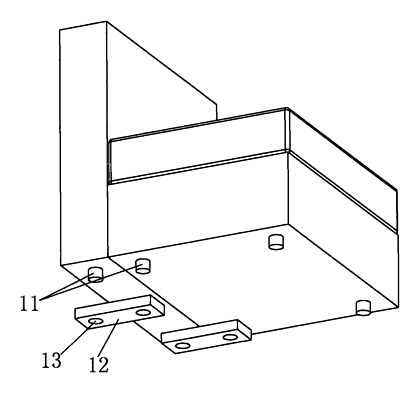
- A connecting plate is positioned below the two members so that it spans their junction.
- Positioning holes on the connecting plate correspond to the locations of the legs. The legs are inserted directly into these holes.
- The upper ends of the positioning holes feature tapered guide mouths, allowing the legs to slide in easily even if they are slightly misaligned.
- The height of the connecting plate is identical to the height of the legs, ensuring the base sits flat.
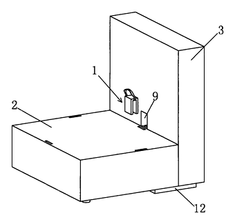
- At the top, the first and second support members are linked together by a connector, specifically a U-clamp.
- The U-clamp has a first foot, a second foot, and a substrate connecting the two feet. These feet insert into a first slot and a second slot on the respective support members, holding them firmly together.
Who it is for
- Modular sofa brands looking for a tool-free way to keep sectional pieces locked together on hardwood or tile floors.
- RTA (ready-to-assemble) furniture companies that want to reduce hardware bags and simplify the customer setup process.
- Commercial seating manufacturers supplying waiting areas or lounges where furniture sections are frequently rearranged but need to stay aligned during use.
- Wholesalers of home furnishings seeking a standardized connection system that fits different module shapes like seats, backrests, and armrests.
How it works
The main parts
| No. | Part | What it does |
|---|---|---|
| 1 | First support member | One section of the furniture, such as a seat portion. |
| 2 | Second support member | The adjacent section, which can be a seat, backrest, or armrest part. |
| 3 | Legs | Extend from the bottom of the support members and insert into the plate. |
| 4 | Connecting plate | Spans the junction of the two members at the bottom to align them. |
| 5 | Positioning holes | Holes on the connecting plate sized to receive the legs. |
| 6 | Tapered guide mouths | Formed at the upper ends of the positioning holes to guide the legs in. |
| 7 | U-clamp | A connector with a substrate and two feet used to link the tops of the members. |
| 8 | Slots (first and second) | Receptacles on the support members where the feet of the U-clamp insert. |
| 9 | Escape groove | A recess on the side of the second support member where the second slot is located. |
Assembly steps
- Place the modules - set the first support member and the second support member side by side in the desired layout.
- Position the plate - slide the connecting plate underneath so it crosses the junction between the two members.
- Insert the legs - lower the modules so the legs align with the positioning holes. The tapered guide mouths funnel the legs into the holes until the plate rests flush with the floor.
- Attach the U-clamp - press the U-clamp over the top edges of the support members, inserting its first foot into the first slot and its second foot into the second slot within the escape groove.
- Check stability - the furniture is now secured at the base by the plate and at the top by the U-clamp.
Applications
Sectional sofas in living rooms
Homeowners frequently push sectional sofa pieces together, but daily use causes them to drift apart. The connecting plate under the legs prevents lateral movement, while the U-clamp keeps the top edges flush. This eliminates the gap that forms between cushions over time.
Waiting area seating
In clinics or offices, individual chair modules are grouped into rows. Cleaning staff need to move them, but they must remain aligned during business hours. The positioning holes allow quick setup, and the identical height of the plate and legs ensures the row sits level on commercial flooring.
Modular lounge chairs for hospitality
Hotels configure lounge areas differently depending on events. Staff can separate the first and second support members, carry them individually, and rejoin them by dropping the legs into the tapered guide mouths. The U-clamp secures the top without requiring maintenance tools.
Children’s room furniture
Parents arranging modular play seating need connections that do not pinch fingers or require heavy wrenches. The legs sliding into the positioning holes provide a straightforward assembly. The U-clamp snaps into the slots, keeping the units stable when children lean against them.
Where it is less suitable
- Fixed, single-piece frames - furniture built as one solid unit does not need a junction plate or U-clamp.
- Outdoor patio furniture exposed to standing water - the positioning holes could collect rainwater unless drainage features are added in design.
- Extremely heavy industrial workbenches - the plate and U-clamp dimensions would need substantial scaling up, to be confirmed in design, for loads beyond standard seating.
Frequently asked questions
How does the connecting plate keep the furniture stable?
The plate is placed under the junction where the first and second support members meet. The legs of both members insert into positioning holes on the plate. Because the plate spans across both modules, it prevents them from sliding apart laterally on the floor.
Do I need tools to assemble the modules?
The patent describes legs inserting directly into the positioning holes and a U-clamp snapping into slots at the top. No threaded fasteners or wrenches are mentioned in the basic structure, making it a tool-free assembly process.
What is the purpose of the tapered guide mouths?
The upper ends of the positioning holes are shaped like funnels. When lowering the furniture modules onto the plate, the tapers catch the legs and guide them into the holes even if the alignment is slightly off.
Can the modules be different shapes?
Yes. The patent specifies that the first support member can be a seat portion, while the second support member can be another seat portion, a backrest, or an armrest part. This allows mixed configurations.
How does the U-clamp attach at the top?
The U-clamp has a substrate connecting two feet. One foot inserts into a slot on the edge of the first support member’s upper surface, and the other foot inserts into a slot on the side of the second support member, which may sit inside an escape groove.
Is the connecting plate visible when the furniture is assembled?
The height of the connecting plate is described as identical to the height of the legs. This means the plate sits flush with the bottom of the legs, resting directly on the floor and remaining largely hidden beneath the furniture frame.
What materials are used for the plate and clamp?
The patent text does not specify materials. Material selection—such as stamped steel, aluminum, or molded plastic—is set in design and confirmed on prototypes based on the weight of the furniture and the required durability.
Can this design be made and sold in the US?
The patent was filed only in China and has expired, so it does not restrict the design in the US or in China. Modular furniture connections may be covered by other US patents held by various companies - see Patent & Production - so we recommend a freedom-to-operate check before volume production.
Are you affiliated with the patent owner?
No. IP2M is an independent design and manufacturing service working from the public patent document.
Request a quote
Click Request a Quote below to see our email address - copy it, or open your email app with a ready-made message. Please mention patent CN205876899U in the subject.
Helpful details to include:
- Your company and channel (modular sofa brand, RTA furniture maker, commercial seating supplier, wholesaler)
- Module types being connected (e.g., seat to seat, seat to armrest)
- Leg shape and diameter to match the positioning holes
- Preferred material for the connecting plate and U-clamp
- Estimated quantity per order
- Timeline - when you need prototypes and the target date for the first shipment
You can also reach us at (332) 203-9997.
Explore this product
Interested in building this?
Tell us your target market, quantity and timeline. We reply with options for prototyping, small-batch runs or volume production.
Send your inquiry to
Please put CN205876899U in the subject line and tell us your company, country, estimated quantity and timeline.
Prefer to talk? Call (332) 203-9997.
More product-ready patents
All Furniture, Bedding & Storage patents →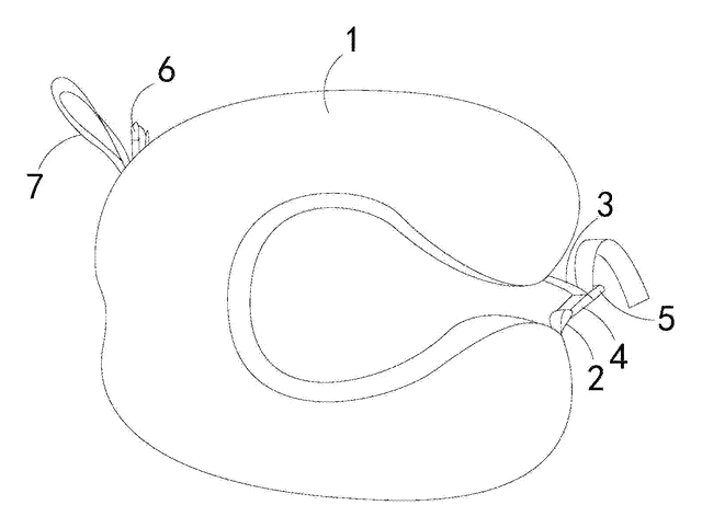
Furniture, Bedding & Storage
Roll-Up Travel Neck Pillow with Buckles
U-shaped travel pillow with a front buckle and a back buckle that holds it rolled up for carrying.
Patent CN206543091U
Furniture, Bedding & Storage
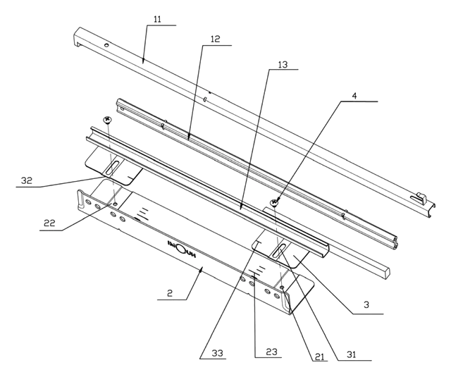
Width-Adjustable Slide Rail for Pull-Out Baskets
Basket slide rail on a slotted, scaled adjusting plate, so one pull-out basket fits several cabinet widths.
Patent CN208909382U
Furniture, Bedding & Storage
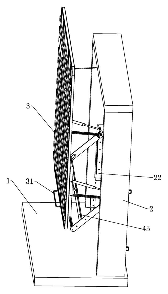
Lift-Up Storage Bed with Four-Bar Linkage That Slides the Deck Away from the Headboard
Storage bed deck that rises on four-bar linkages and gas springs, clearing the headboard as it opens.
Patent CN210870645U
Furniture, Bedding & Storage
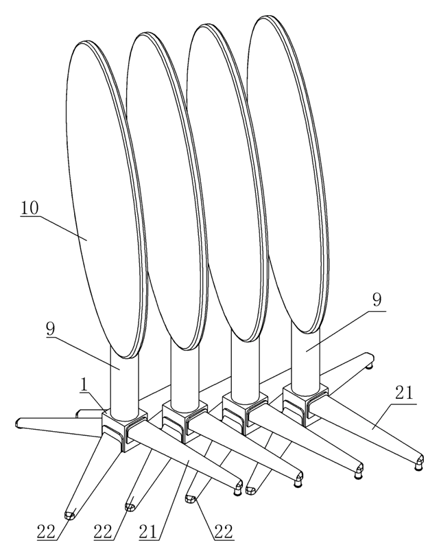
Self-Leveling, Nesting Table Base with a Torsion-Ring Leg Hub
Four-leg base that self-levels through a torsion-ring hub and nests sideways with flip-top tables.
Patent CN211483640U
Furniture, Bedding & Storage
Rack-and-Pinion Synchronized Drawer Slide with a Folded-In Fixed Rail
Full-extension drawer slide: a pinion between two racks keeps the rails moving in step.
Patent CN206314843U
Furniture & Bedding
Dual-Zone Split-Spring Mattress with Removable Fabric Cover
Half-pocket, half-standard spring mattress sharing one base plate, with a removable cover.
Patent CN208355064U
Browse by category
- Apparel & Accessories (22)
- Baby & Kids (16)
- Bags & Luggage (9)
- Bath & Personal Care (16)
- Car Accessories (10)
- Furniture, Bedding & Storage (12)
- Garden & Outdoor (18)
- Health & Wellness (8)
- Home, Kitchen & Cleaning (24)
- Lighting (12)
- Packaging & Containers (6)
- Pet Products (6)
- Phone & Camera Accessories (4)
- Retail Display (13)
- School, Office & Art (19)
- Sports & Recreation (25)
- Tools & Workshop (27)
- Toys & Games (12)
This page is based on the public patent document CN205876899U, assigned to Zhejiang Malati Intelligent Furniture Technology Co Ltd. IP2M is an independent manufacturing service and is not affiliated with, endorsed by or licensed by the patent owner. Images marked as concept renderings are illustrations, not photos of an existing product. Patent status information is provided for reference only and is not legal advice; confirm freedom to operate for your market before production. Full disclaimer.