
Patent CN205922296U
Updated October 25, 2026Flat Pressure-Compensating Drip Emitter with Built-In Filter Chamber for Drip Tape
Drip tape waters row crops, greenhouses and gardens through small plastic emitters molded into the tape every few inches. On long rows or slopes the pressure drops along the line, so ordinary emitters give more water near the inlet than at the far end. Pressure-compensating emitters fix this with a rubber diaphragm, but they are usually bulkier. This flat emitter is designed to be welded inside thin drip tape. Water comes in through a grille on the top face into a chamber that holds back grit, runs along labyrinth channels on the underside that break up the flow, and then passes a flexible diaphragm. As line pressure rises, the diaphragm presses harder and narrows the path, keeping the output steady.
- China utility model - expired
- No filings outside China
- Drip irrigation & greenhouse supplies
- Molded PE emitter, silicone or EPDM diaphragm
Splat! What let you down?
💧
Pressure-compensating
A flexible diaphragm narrows the path as pressure rises, keeping output steady along the row.
🧹
Built-in filter chamber
An inlet grille and a ring inside the chamber hold back grit before it reaches the channels.
〰️
Labyrinth flow paths
Toothed labyrinth channels on the underside break up the flow and resist clogging.
📏
Flat, tape-ready shape
A flat strip emitter made to be welded inside thin-wall drip tape.
Bring this product to market
- ✓ Patent vetted China-only family and legal status checked
- 2 Product brief · now How it works, uses and options written up
- 3 Prototype First samples for buyers to review
- 4 Pilot run Small first batch for launch customers
- 5 Volume production Repeat orders at scale
Buyer interest
– of 100 buyers needed to start prototyping
One click, no sign-up. Each vote is one real visitor, and products with the most interest go to prototyping first.
Build team: no members yet. Need a partner, co-funding or skills to build this? Join and we introduce the team once it forms.
The problem
Drip tape delivers water through emitters spaced along a thin plastic hose. On long rows, uneven ground or high-volume systems the water pressure falls with distance, so plants near the inlet get more water than those at the end. Pressure-compensating emitters solve this with a flexible diaphragm, but they tend to be cylindrical or bulky parts that suit thick-wall pipe more than economical thin-wall tape. Fine sand and silt in the water also clog the narrow channels.
The solution
The patent packs a filter, labyrinth and diaphragm into a flat strip:
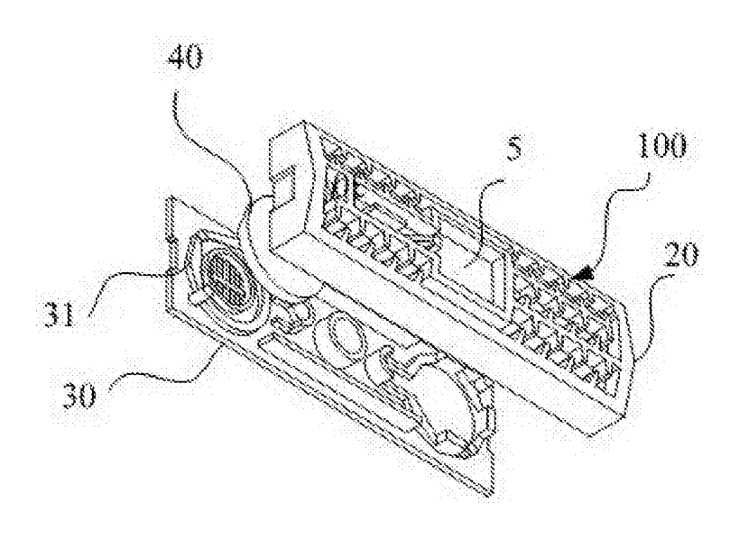
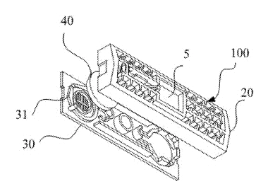
- The dripper body (100) has an upper surface (30) with a water inlet grille (31) and a lower surface (20) that is welded against the inside of the tape.
- Inside the body is a water chamber, divided by an elastic diaphragm (40) into a pressure-compensation cavity and a filter cavity.
- A ring (33) in the filter cavity splits it into an inlet tank (33-1) and an outlet tank (33-2), so grit settles before water moves on.
- From the filter cavity, water leaves through a first outlet (1) into an external labyrinth channel (8) on the lower surface, lined with turbulence teeth. In a two-stage version, water runs through a first external labyrinth (8-1), an internal labyrinth and a second external labyrinth (8-2).
- Through a first inlet (2) the water enters the pressure-compensation cavity. Line pressure pushes the diaphragm, which controls the flow to the second outlet (3).
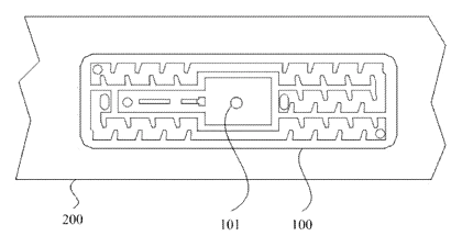
- From there the water reaches a perforated slot (5) under the tape’s outlet hole; dividing plates spread it along the slot.
Who it is for
- Drip tape manufacturers that extrude tape and insert emitters, looking for a flat pressure-compensating emitter design.
- Irrigation brands selling drip lines to vegetable growers, orchards and greenhouse operators.
- Agricultural distributors supplying farms with long rows or rolling ground where pressure varies.
- Garden and landscape irrigation companies offering drip kits for raised beds and hedges on slopes.
How it works
The main parts
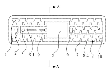
| No. | Part | What it does |
|---|---|---|
| 100 | Dripper body | Flat strip welded inside the tape. |
| 31 | Inlet grille | Lets water in from the tape, keeps large particles out. |
| 33 | Ring | Splits the filter cavity into inlet and outlet tanks. |
| 40 | Elastic diaphragm | Flexes with pressure to keep flow steady. |
| 8 | Labyrinth channels | Toothed paths that break up flow. |
| 1, 3 | First and second outlets | Lead water through the stages. |
| 2 | First inlet | Feeds the compensation cavity. |
| 5 | Perforated slot | Collects water under the tape’s outlet hole. |
Water path
- Line water enters through the inlet grille into the filter cavity.
- Grit settles at the ring between the inlet and outlet tanks.
- Water runs through the labyrinth channels, which drop its pressure.
- The diaphragm regulates flow into the outlet path as line pressure changes.
- Water drips out of the slot through the hole in the tape.
Applications
Row-crop vegetables
Long beds of tomatoes, peppers and lettuce get even watering from the head of the row to the end.
Greenhouses and tunnels
Growers on raised benches or long tunnels need uniform output to keep plants uniform.
Orchards and vineyards on slopes
Pressure compensation helps where the line runs up and down hills.
Strawberries and berries
Plastic-mulched beds use drip tape under the film; clog resistance matters with well or pond water.
Home gardens and raised beds
Drip kits for gardens benefit from even output when several beds share one faucet.
Where it is less suitable
- Very dirty water without a main filter - the built-in chamber helps, but the system still needs a screen or disc filter.
- Thick-wall permanent drip line - cylindrical emitters are often preferred in heavy-wall pipe.
- Very low pressure gravity systems - compensating diaphragms need a minimum pressure to work.
Frequently asked questions
How does it keep flow even along a long row?
Water passes a flexible diaphragm on its way out. As line pressure rises, the diaphragm presses harder and narrows the path, so emitters near the inlet do not give much more water than those at the end.
How does it resist clogging?
Water enters through a grille, settles in a filter cavity split by a ring, and then runs through toothed labyrinth channels whose turbulent flow helps keep particles moving. A main system filter is still needed.
What flow rates are possible?
The patent does not fix a flow rate. Flow classes are set by the labyrinth and outlet sizes in design and confirmed by pressure-flow tests.
Can it be inserted on our tape line?
The flat strip is made to be welded inside thin-wall tape. Emitter width, height and feed orientation are matched to your insertion equipment on samples.
What is the diaphragm made of?
The patent calls it an elastic diaphragm. Silicone or EPDM is typical, chosen for the pressure range and for resistance to fertilizer and chlorine.
Can you supply finished drip tape?
Yes. We can quote emitters alone for tape makers, or finished rolls by wall thickness, diameter and emitter spacing.
Can this design be made and sold in the US?
The patent was filed only in China and has expired, so it does not restrict the design in the US or in China. Drip emitters may be covered by other US patents - see Patent & Production - so we recommend a freedom-to-operate check before volume production.
Are you affiliated with the patent owner?
No. IP2M is an independent design and manufacturing service working from the public patent document.
Request a quote
Click Request a Quote below to see our email address - copy it, or open your email app with a ready-made message. Please mention patent CN205922296U in the subject.
Helpful details to include:
- Your company and channel (tape maker, irrigation brand, distributor, garden brand)
- Flow classes and pressure range
- Tape specification (wall, diameter, spacing) or emitters only
- Water quality and chemigation use
- Estimated quantity and target price
- Timeline - when you would like samples and the first shipment
You can also reach us at (332) 203-9997.
Explore this product
Interested in building this?
Tell us your target market, quantity and timeline. We reply with options for prototyping, small-batch runs or volume production.
Send your inquiry to
Please put CN205922296U in the subject line and tell us your company, country, estimated quantity and timeline.
Prefer to talk? Call (332) 203-9997.
More product-ready patents
All Garden & Outdoor patents →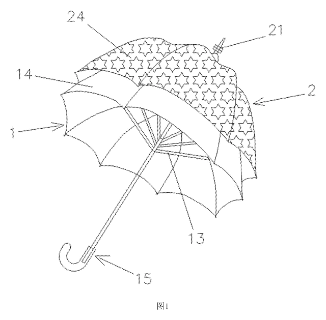
Garden & Outdoor
2-in-1 Parent & Child Umbrella
Full-size umbrella with a nested smaller umbrella on top - a rotating decorative layer that detaches into a kid-size umbrella.
Patent CN205611962U
Garden & Outdoor
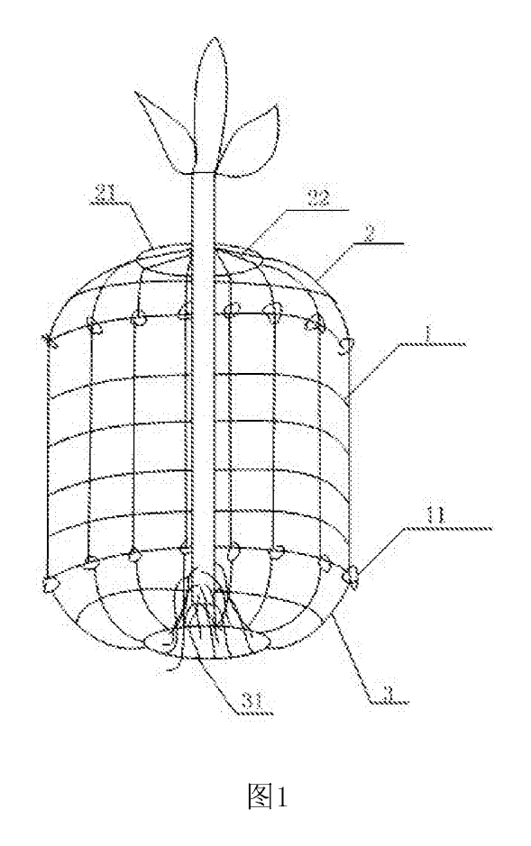
Wire-Mesh Tree Root & Trunk Guard Against Rodents
Three-part wire-mesh guard that protects the roots and lower trunk of young trees from burrowing and gnawing animals.
Patent CN206808261U
Garden & Outdoor
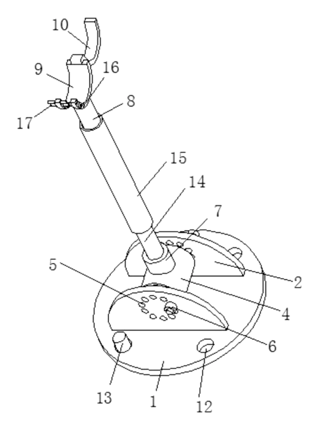
Adjustable-Angle Tree Support Prop
Tree prop with a pinned base, angle-locking hinge, twist-adjust tube and a locking trunk ring.
Patent CN208370491U
Garden & Outdoor
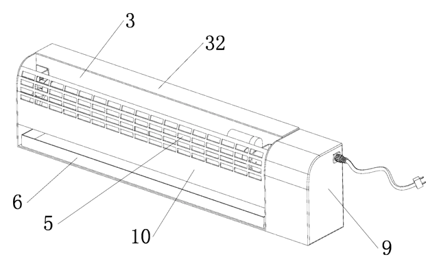
Self-Renewing Glue-Roller Mosquito Trap
UV insect trap with a glue roller that re-coats itself and scrapes the catch into a tray - no glue boards.
Patent CN217038569U
Garden & Outdoor
Cam-Lock Telescopic Pole for Garden Power Tools
Telescopic pole for garden power tools with cam-lever locks and a spring-button, tear-drop head socket.
Patent CN205812889U
Garden & Outdoor
Mosquito Fan That Listens for Mosquitoes Before It Sprays
Fan with a scanning microphone dish that mists repellent only when it hears mosquitoes.
Patent CN208708542U
Browse by category
- Apparel & Accessories (22)
- Baby & Kids (16)
- Bags & Luggage (9)
- Bath & Personal Care (16)
- Car Accessories (10)
- Furniture, Bedding & Storage (12)
- Garden & Outdoor (18)
- Health & Wellness (8)
- Home, Kitchen & Cleaning (24)
- Lighting (12)
- Packaging & Containers (6)
- Pet Products (6)
- Phone & Camera Accessories (4)
- Retail Display (13)
- School, Office & Art (19)
- Sports & Recreation (25)
- Tools & Workshop (27)
- Toys & Games (12)
This page is based on the public patent document CN205922296U, assigned to Qingdao Xindacheng Plastic Machinery Co., Ltd.. IP2M is an independent manufacturing service and is not affiliated with, endorsed by or licensed by the patent owner. Images marked as concept renderings are illustrations, not photos of an existing product. Patent status information is provided for reference only and is not legal advice; confirm freedom to operate for your market before production. Full disclaimer.