At a glance
| Patent number | CN205922296U (application CN201620878370) |
| Type | China utility model (实用新型) - protects product shape and structure |
| Original title | Inner-insert pressure-compensating dripper and drip irrigation tape (内镶片式压力补偿滴头及滴灌带) |
| Patent owner | Qingdao Xindacheng Plastic Machinery Co., Ltd. |
| Inventors | Li Chengxiu, Wang Jingchang, Li Guiying |
| Filing date | 2016-08-15 |
| Grant date | 2017-02-08 |
| Status (China) | Expired - a China utility model lasts at most 10 years from filing; the term ended on 2026-08-15 |
| Patent family | Chinese filings only - no US, European, Japanese, PCT or other filings listed |
| Cited by | 7 later documents |
| Source | Google Patents (search for CN205922296U) |
What the claims cover, in plain language
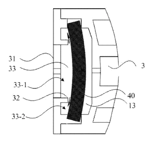
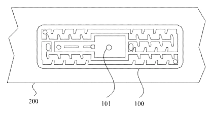
Claim 1 - an inner-insert pressure-compensating dripper whose lower surface carries an external labyrinth channel, a perforated slot, first and second outlets and a first inlet, and whose upper surface carries an inlet grille. Inside is a water chamber divided by an elastic diaphragm into a compensation cavity and a filter cavity. Water flows grille - filter cavity - first outlet - labyrinth - first inlet - compensation cavity - second outlet - slot.
Claims 2-3 - two external labyrinths linked by an internal labyrinth, all with turbulence teeth. Claim 4 - spaced dividing plates between the second outlet and the slot. Claim 5 onward - a ring around the grille that divides the filter cavity into an inlet tank and an outlet tank, and a drip tape containing the dripper.
This is a simplified reading for orientation only. The legal scope is defined by the exact claim wording in the official Chinese document.
What this means for US production
This patent was filed only in China and has expired, so it no longer restricts anyone in China either. It has no US or other foreign counterpart.
Two points to settle early:
- Other patents may exist. Pressure-compensating emitters are a heavily patented field led by large irrigation companies in the US and Israel, so a freedom-to-operate (FTO) review of the diaphragm, labyrinth and filter layout is essential before tooling.
- Flow class. Emitter flow rate, compensation range and spacing are set together with the tape line; molds are built per flow class.
Customization and manufacturing
What can be customized
| Area | Options |
|---|---|
| Flow rate | Several nominal flow classes, set by labyrinth and outlet size |
| Compensation range | Diaphragm thickness and hardness for the target pressure range |
| Materials | PE emitter body; silicone or EPDM diaphragm; UV and chemical resistance |
| Tape | Wall thickness, diameter and emitter spacing on the tape line |
| Filtration | Grille slot size and ring design for local water quality |
| Packaging | Bulk emitters for tape makers or finished rolls |
Things to plan for (US market)
- ISO 9261 - emitter and emitting-pipe specification and test methods (flow uniformity, pressure-flow curve).
- ASABE S553 - the US standard for collapsible emitting hose (drip tape), used by growers and specifiers.
- Chemigation - fertilizer and chlorine injection is common; emitter and diaphragm materials are tested for chemical resistance.
- California Prop 65 - plastic and rubber compounds are screened for retail kits.
How a project runs
- Inquiry - flow classes, pressure range, tape type and quantity.
- Design - labyrinth geometry, diaphragm cavity, grille and ring.
- Prototype - emitter samples measured for pressure-flow curves and coefficient of variation.
- Pilot run - samples inserted into tape on the customer’s line; clog tests with dirty water.
- Production - multi-cavity emitter molding, diaphragm molding and automated assembly.
Quantities & timeline
The emitter body needs high-cavity precision molds, the diaphragm needs a silicone or EPDM compression mold, and assembly runs on automated feeders that match the tape line. Flow testing and mold balancing take most of the development time. Send us your flow classes, pressure range, tape specification, quantity and target price and we will reply with options.
Patent drawings
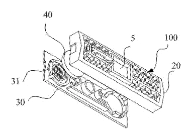
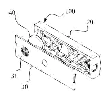
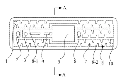
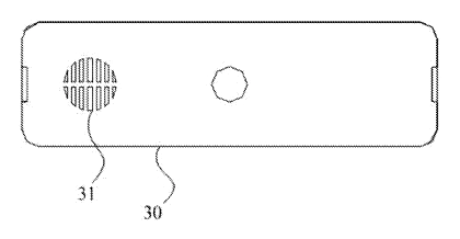
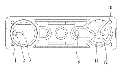
Drawings reproduced from the public patent document for reference.