At a glance
| Patent number | CN206086633U (application CN201620600334) |
| Type | China utility model (实用新型) - protects product shape and structure |
| Original title | Safety belt alarming device (安全带警示装置) |
| Patent owner | Dongguan Jiahong Automobile Products Co ltd |
| Inventors | Lin Yongfa |
| Filing date | 2016-06-16 |
| Grant date | 2017-04-12 |
| Status (China) | Expired - a China utility model lasts at most 10 years from filing; the term ended on 2026-06-16 |
| Patent family | Chinese filings only - no US, European, Japanese, PCT or other filings listed |
| Cited by | 6 later documents (including Autoliv Development Ab patents WO2024194427A1, WO2024194428A1, WO2024245899A1) |
| Source | Google Patents (search for CN206086633U) |
What the claims cover, in plain language
Claim 1 - A safety belt alarming device sheathed on a vehicle safety buckle seat. It includes a sheath body with an upper cover and a lower cover that assemble to form an opening. A light emitting module is located inside the body corresponding to the opening. A transmission element is mounted on the light module side to direct the light out through the opening.
Claim 2 - Adds a protection cap covering the lower cover relative to the buckle seat. Claim 3 - The transmission element has a fixture; the light module has a fixing hole for insertion connection. Claim 4 - The upper cover has a first connecting portion and the lower cover has a second connecting portion that clamp together to form the sheath. Claim 5 - Includes adhesive components between the covers and the buckle seat to strengthen attachment. Claim 6 - The light module is electrically connected via wires to a detection circuit on the buckle. Claim 7 - The module has a control board and multiple light-emitting components. When the buckle tongue is inserted, the detection circuit sends a signal to adjust luminous intensity. Claim 8 - The transmission element is a frame-shaped structure aligned with the opening; the control board is also frame-shaped.
This is a simplified reading for orientation only. The legal scope is defined by the exact claim wording in the official Chinese document.
What this means for US production
This patent was filed only in China and has expired, so it no longer restricts anyone in China. It has no US or other foreign counterpart.
Two points to settle early:
- Other patents may exist. Automotive safety systems are heavily patented globally. Major suppliers like Autoliv have cited this work in recent filings (WO2024…), suggesting active development in similar fields. A freedom-to-operate (FTO) review is recommended to check for newer US patents covering specific LED integration methods or buckle signaling logic.
- Electrical Safety Standards. Connecting directly to a vehicle’s detection circuit involves electrical engineering. Ensuring the wiring and control board meet automotive electrical standards (such as ISO 6722 for cables or SAE J1113 for EMC) is critical for any US market entry.
Customization and manufacturing
What can be customized
| Area | Options |
|---|---|
| Light Source | Color temperature (white, amber, red), LED count, brightness levels |
| Casing Material | ABS, PC, or TPU for flexibility; matte or glossy finish |
| Shape/Fit | Dimensions to match specific buckle brands (e.g., TRW, Autoliv, Bosch) |
| Signal Logic | Dimming curve, blink patterns, or simple on/off based on sensor input |
| Mounting | Clip strength, adhesive type, screw vs. snap-fit assembly |
| Wiring | Connector type (plug-and-play vs. solder), wire length, insulation rating |
Things to plan for (US market)
- FMVSS 209 / 208 - While this is an accessory, it must not interfere with the primary function of the seat belt restraint system. Any modification to the buckle housing requires careful validation to ensure it does not affect the mechanical locking strength or release mechanism.
- EMC/EMI Compliance - Electronic components installed in vehicles must comply with FCC Part 15 if they emit radio frequencies, though passive LEDs typically do not. However, proximity to vehicle ECUs requires shielding considerations.
- Temperature Range - Automotive-grade components must withstand extreme heat (dashboard exposure) and cold (-40°C to +85°C typical requirement).
- Durability Testing - UV resistance for plastics exposed to sunlight; vibration resistance for road conditions.
How a project runs
- Inquiry - Provide buckle model, desired light behavior, and volume estimates.
- Design - CAD modeling of the casing to fit the specific buckle geometry; PCB layout for the controller.
- Prototype - 3D printed housings and hand-soldered PCBs for fitment and basic function testing.
- Validation - Environmental stress screening (heat/cold/vibration) and electrical continuity checks.
- Production - Injection molding for casings, automated PCB assembly, manual wiring and final assembly.
Quantities & timeline
Injection molds for the upper/lower covers take 4-6 weeks. PCB prototyping takes 1-2 weeks. Final assembly line setup depends on complexity. Send us your buckle model photos, desired light color, and estimated annual quantity and we will reply with options.
Production notes
Tooling and process
The upper and lower covers are likely ABS or PC injection moldings, with a separate tool for the protection cap. PCB assembly covers the small control board, and the light module is typically assembled with a frame-shaped transmission element and wired to the buckle detection circuit.
Cost drivers
Tooling is typically driven by the number of cover variants needed for different buckle geometries. PCB assembly and LED binning add cost, as does incoming inspection of the seat-buckle interface. Low volumes per buckle model usually mean higher unit amortization.
Prototyping path
Prototyping typically starts with 3D-printed covers on a representative buckle, followed by a hand-built PCB and LED module for fit and light-output checks. Environmental samples usually follow once the housing snaps and adhesive bond are confirmed.
What we would change before tooling
We would verify wall thickness and snap-fit retention around the opening, since a loose sheath can rattle or shift on the buckle. Wire routing and strain relief at the detection-circuit connection would also be reviewed before mold release.
Common failure points
Light leakage at the opening and uneven brightness across the frame are likely cosmetic issues. Adhesive failure between the covers and the buckle seat is a risk under heat cycling, and wire fatigue typically appears if the harness is not strain-relieved.
Patent drawings
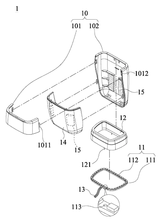
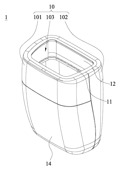
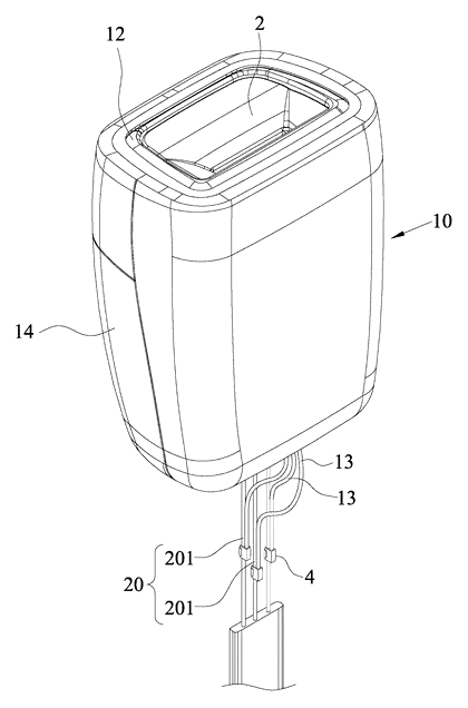
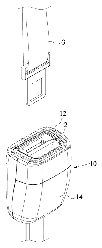
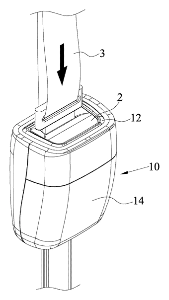
Drawings reproduced from the public patent document for reference.