
Patent CN206324044U
Updated October 26, 2026Wireless-Powered Aquarium with Internal Induction Receiver
Running power cables into a fish tank means drilling holes in the glass or leaving gaps in the lid where water can splash out and moisture can creep along the wires. This wireless-powered aquarium replaces those cables with electromagnetic induction. A flat transmitter module sits outside the tank, usually under the bottom support, and sends energy through the glass to a sealed receiver module inside. That receiver feeds power directly to the lighting, aeration and sensor modules submerged in the water, so the tank stays completely closed with no exposed electrical connections near the water.
- China utility model - lapsed
- No filings outside China
- Pet & aquarium equipment
- Electromagnetic induction power transfer
Splat! What let you down?
⚡
Wireless power transfer
Electromagnetic induction passes energy through the glass, removing cables from the water.
💧
Sealed enclosure
No drilled holes or lid gaps for wires, reducing splash-out and moisture risks.
🐟
Internal modules
Lighting, aeration and detection units run directly off the internal receiver board.
🔧
Detachable transmitter
The external transmitter pad can be fixed at various positions under the tank base.
Bring this product to market
- ✓ Patent vetted China-only family and legal status checked
- 2 Product brief · now How it works, uses and options written up
- 3 Prototype First samples for buyers to review
- 4 Pilot run Small first batch for launch customers
- 5 Volume production Repeat orders at scale
Buyer interest
– of 100 buyers needed to start prototyping
One click, no sign-up. Each vote is one real visitor, and products with the most interest go to prototyping first.
Build team: no members yet. Need a partner, co-funding or skills to build this? Join and we introduce the team once it forms.
The problem
Standard aquariums require electrical cords for submersible pumps, air stones, heaters and lights to pass through the lid or a drilled hole in the glass. These openings compromise the seal, allow water to splash onto live electrical contacts, and create paths for moisture to travel along the wire insulation. Over time, salt spray or humidity can corrode connectors, and any fault in a cable submerged in water presents a shock hazard to both the keeper and the aquatic life. According to the patent, the objective is to provide a wireless power supply that produces a continuous and steady current while improving safety by eliminating physical electrical connections inside the tank.
The solution
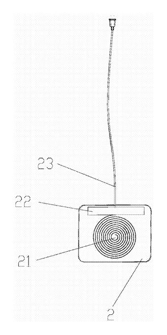
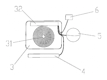
- An electromagnetic induction transmitter module (2) is placed on the outside of the aquarium (1), typically beneath the bottom panel. It contains a transmitting coil (21), a circuit board (22) and a power line (23) that connects to mains or a DC adapter.
- An electromagnetic induction receiver module (3) is positioned on the inside of the aquarium, aligned directly opposite the transmitter. It holds a receiving coil (31) and its own circuit board (32), all enclosed in a sealed, flat housing.
- When the transmitter is energized, the transmitting coil generates an alternating magnetic field that passes through the glass wall. The receiving coil picks up this field and induces a current, which the internal circuit board conditions into usable power.
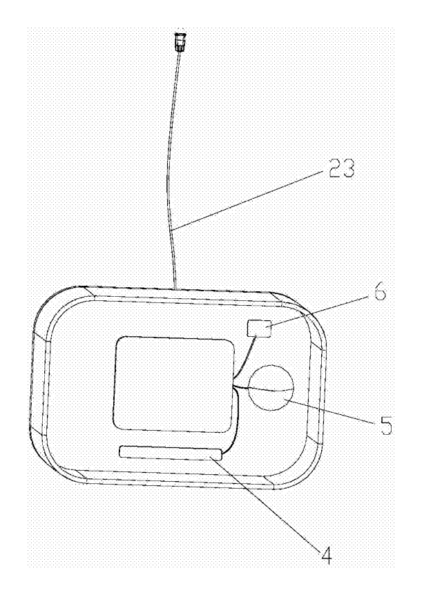
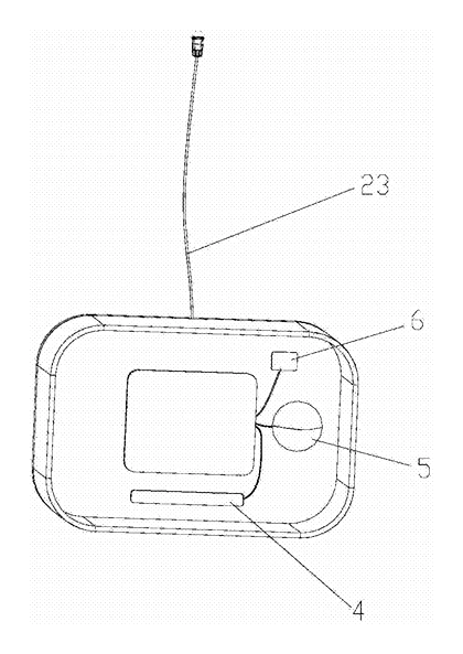
- A lighting module (4), an oxygen processing module (5) and a detection module (6) are wired to the receiver’s circuit board inside the tank. They draw all their operating power from the induced current, so no separate cord enters the water.
- The bottom of the aquarium (1) features a surrounding support (11) whose height exceeds the thickness of the transmitter module, allowing the transmitter to sit flush underneath without raising the tank unevenly.
Who it is for
- Aquarium equipment brands looking to differentiate their product lines with cable-free tank designs that appeal to modern home décor buyers.
- Custom acrylic and glass tank fabricators who want to offer built-in wireless power as a premium option for reef or planted tanks where clean sightlines matter.
- Pet product distributors and Amazon sellers targeting hobbyists willing to pay more for safer, leak-proof enclosures with integrated electronics.
- Educational and public display facilities that maintain multiple small tanks and benefit from standardized, easily swappable wireless power pads instead of tangled cord clusters.
How it works
The main parts
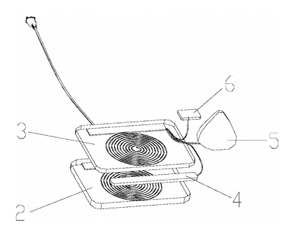
| No. | Part | What it does |
|---|---|---|
| 1 | Aquarium | The glass or acrylic tank holding water; its bottom has a raised support (11). |
| 2 | Transmitter module | Flat unit outside the tank containing the transmitting coil (21), circuit board (22) and power line (23). |
| 3 | Receiver module | Sealed flat unit inside the tank containing the receiving coil (31) and circuit board (32). |
| 4 | Lighting module | LED or lamp array connected to the receiver board, mounted on the inner wall or bottom. |
| 5 | Oxygen processing module | Aeration pump or air stone driver connected to the receiver board, located at the inner bottom. |
| 6 | Detection module | Sensor unit (e.g., temperature or water level) connected to the receiver board, placed on the wall or middle section. |
| 11 | Support | Raised rim around the tank bottom, taller than the transmitter module thickness. |
| 21 | Transmitting coil | Center-mounted coil that generates the magnetic field. |
| 22 | Transmitter board | Edge-mounted electronics driving the coil. |
| 31 | Receiving coil | Aligned opposite the transmitting coil to capture the field. |
Operating steps
- Place the transmitter - position the flat transmitter module (2) under the aquarium bottom, resting within the space created by the support rim (11). It can be detachably secured at the center or edge.
- Align the receiver - the sealed receiver module (3) is already installed inside the tank, positioned so its receiving coil (31) faces the transmitting coil (21) through the glass.
- Connect power - plug the power line (23) of the transmitter into a suitable AC adapter or DC source.
- Induction begins - the transmitter circuit board (22) drives the transmitting coil (21) to produce an alternating electromagnetic field. This field crosses the glass barrier.
- Power delivery - the receiving coil (31) converts the field back into electrical current. The receiver circuit board (32) regulates this current and supplies it to the lighting module (4), oxygen processing module (5) and detection module (6).
- Operation - all internal devices run continuously without any physical wire penetrating the tank walls.
Applications
Home freshwater and planted tanks
Hobbyists setting up living-room aquariums often struggle with visible cords running down the back or over the rim. By placing the transmitter pad under the stand and sealing the receiver inside, the tank presents a clean, cord-free appearance. The integrated lighting and aeration modules handle basic needs without aftermarket clutter.
Marine reef micro-tanks
Small reef systems require intense lighting and constant water movement but have very limited space for cable glands. A wireless receiver module mounted on the inner bottom can drive compact LED arrays and small circulation drivers. Removing drilled holes also eliminates a common failure point where saltwater creeps along silicone seals.
Classroom and laboratory setups
Schools maintaining several small observation tanks benefit from standardized wireless bases. Students can lift a tank off its transmitter pad for cleaning without unplugging multiple waterproof connectors. The detection module provides basic monitoring data fed through the same internal power bus.
Retail and restaurant displays
Commercial venues use aquariums as decorative elements where exposed wiring looks unprofessional and poses a trip hazard. The flush-mounted transmitter hides entirely beneath the display counter, while the sealed receiver keeps all electrical components safely behind glass, away from customer contact.
Quarantine and hospital tanks
When treating sick fish, keepers frequently move livestock between bare-bottom quarantine tubs. A portable transmitter pad can be slid under different containers, powering a temporary receiver-equipped light and air module without needing dedicated outlets for each tub.
Where it is less suitable
- Large-volume commercial systems - high-wattage filtration heaters and large return pumps draw more power than typical near-field induction pads efficiently deliver; thick glass further reduces coupling.
- Tanks with metal frames or foil backgrounds - conductive materials between the coils block or absorb the magnetic field, preventing reliable power transfer.
- Budget entry-level kits - the added cost of dual coils, sealed receiver housings and custom PCBs makes this approach impractical for mass-market starter aquariums sold at low price points.
Frequently asked questions
How does power get into the tank without wires?
The patent describes an electromagnetic induction transmitter module placed outside the aquarium and a receiver module sealed inside. The transmitter coil generates a magnetic field that passes through the glass wall, inducing a current in the receiver coil. That current powers the internal lighting, aeration and sensor modules directly.
Does the glass thickness affect performance?
Yes. Electromagnetic induction efficiency drops as the distance between the transmitting and receiving coils increases. The patent does not specify a maximum glass thickness, so the operating gap is set in design based on the chosen coil diameter, number of turns and driving frequency. Thicker acrylic or glass panels require larger coils or higher power to compensate.
What happens if the tank is lifted off the transmitter?
The magnetic coupling breaks immediately when the receiver moves out of alignment with the transmitter. According to the patent, the transmitter is detachably secured to the bottom of the aquarium within a surrounding support rim. If the tank is lifted for maintenance, the internal modules simply lose power and shut down safely, similar to unplugging a standard cord.
Can additional devices like heaters be powered this way?
The patent specifically lists a lighting module, an oxygen processing module and a detection module connected to the receiver circuit board. High-wattage devices such as submersible heaters draw significantly more current than LEDs or small air pumps. Whether a heater can be included depends entirely on the total wattage the induction pair is engineered to deliver, which is confirmed on prototypes.
How is the internal receiver kept waterproof?
The patent describes the receiver module as a “surrounding closed” flat plate with the receiving coil and circuit board integrated inside. In manufacturing, this typically means the electronics are either enclosed in a sonically welded plastic shell or fully encapsulated in an epoxy or polyurethane potting compound to prevent water ingress during long-term submersion.
Where exactly do the internal modules mount?
The claims describe several positions. The lighting module mounts on the inner wall or bottom. The detection module sits on the inner wall, middle section or bottom. The oxygen processing module is located at the inner bottom. Exact placement is finalized during the industrial design phase to optimize light spread and water flow.
Can this design be made and sold in the US?
The patent was filed only in China and is lapsed (terminated for non-payment of annual fees in 2024), so it does not restrict the design in the US or in China. Wireless power transfer technologies may be covered by other US patents - see Patent & Production - so we recommend a freedom-to-operate check before volume production.
Are you affiliated with the patent owner?
No. IP2M is an independent design and manufacturing service working from the public patent document.
Request a quote
Click Request a Quote below to see our email address - copy it, or open your email app with a ready-made message. Please mention patent CN206324044U in the subject.
Helpful details to include:
- Your company and channel (aquarium brand, pet distributor, custom tank fabricator, Amazon seller)
- Tank dimensions and material (glass or acrylic, approximate thickness)
- Required internal modules (LED specs, aeration flow rate, sensor types)
- Total estimated power draw for the internal loads
- Estimated quantity and target price
- Timeline - when you would like engineering samples and the first shipment
You can also reach us at (332) 203-9997.
Explore this product
Interested in building this?
Tell us your target market, quantity and timeline. We reply with options for prototyping, small-batch runs or volume production.
Send your inquiry to
Please put CN206324044U in the subject line and tell us your company, country, estimated quantity and timeline.
Prefer to talk? Call (332) 203-9997.
More product-ready patents
All Pet Products patents →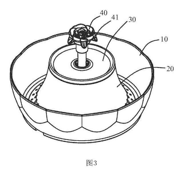
Pet Products
Multi-Pet Fountain Water Dispenser
Round pet fountain with a central flower spray head - several pets drink from any side; water is filtered and circulated.
Patent CN207870035U
Pet Products
Adjustable Snap-Fit Animal Muzzle
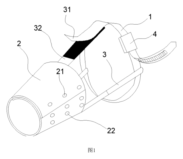
Soft muzzle with snap-adjustable snout sleeve, ratchet neck strap and detachable connecting straps.
Patent CN208523497U
Pet Products
Automatic Cleaning Rodent Rearing Cage with Carousel Tray System
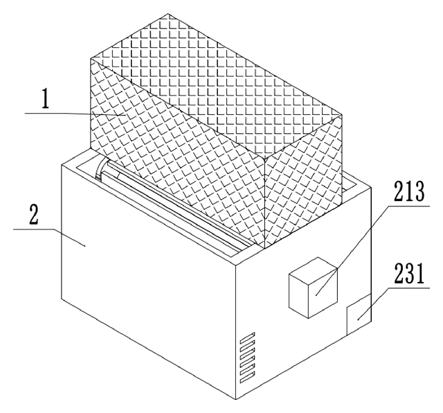
Rodent cage with a rotating tray carousel that washes, UV-sterilizes and dries automatically.
Patent CN118415089B
Pet Products
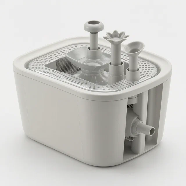
Automatic Pet Drinking Fountain with Interchangeable Water Outlet Heads
Pet fountain with a pressurized pump and swappable shower heads for multiple water flow patterns.
Patent CN207803161U
Pet Products
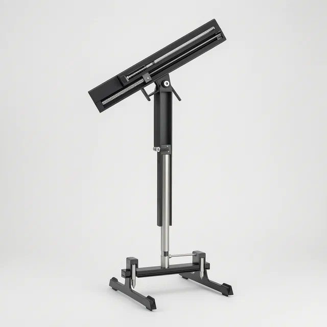
Mechanical Flying Disc Launcher for Pet Dog Training
Spring-loaded flying disc launcher for dogs with adjustable height, angle, and folding base.
Patent CN118614420B
Apparel & Footwear
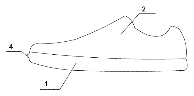
Sensor-Enabled Training Running Shoe with Laser Stride Guide
Training shoe with sole pressure sensors and a toe-mounted laser projecting a stride guide line.
Patent CN206652176U
Browse by category
- Apparel & Accessories (22)
- Baby & Kids (16)
- Bags & Luggage (9)
- Bath & Personal Care (16)
- Car Accessories (10)
- Furniture, Bedding & Storage (12)
- Garden & Outdoor (18)
- Health & Wellness (8)
- Home, Kitchen & Cleaning (24)
- Lighting (12)
- Packaging & Containers (6)
- Pet Products (6)
- Phone & Camera Accessories (4)
- Retail Display (13)
- School, Office & Art (19)
- Sports & Recreation (25)
- Tools & Workshop (27)
- Toys & Games (12)
This page is based on the public patent document CN206324044U, assigned to Guangzhou Cloud Nest Industrial Design Co Ltd. IP2M is an independent manufacturing service and is not affiliated with, endorsed by or licensed by the patent owner. Images marked as concept renderings are illustrations, not photos of an existing product. Patent status information is provided for reference only and is not legal advice; confirm freedom to operate for your market before production. Full disclaimer.