
Patent CN206462545U
Updated October 26, 2026Fully Automatic Reverse-Folding Umbrella with Screw-Driven Mechanism
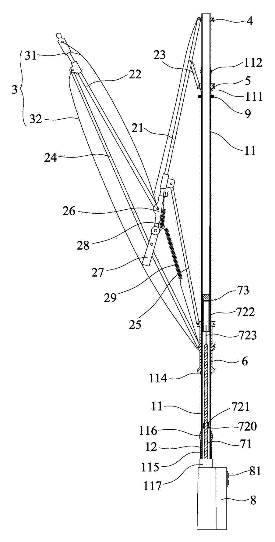
Standard umbrellas fold outward, leaving the wet rain-facing surface exposed to drip on car seats, bags, and clothes when you step indoors. This reverse-folding design solves that by collapsing the canopy inward toward the handle, enclosing the wet side inside the dry inner cloth. The entire opening and closing sequence is powered by a motor housed in the handle. Pressing a button activates a forward or reverse drive that turns a screw mandrel, moving an ejector sleeve and outer tube to deploy or retract the frame automatically without manual pulling or pushing.
- China utility model - in force
- No filings outside China
- Umbrellas & sticks
- Motor-driven screw mechanism, reverse-folding frame
Splat! What let you down?
⚙️
Motor-driven operation
A power source in the handle turns a screw mandrel to open and close the canopy automatically.
🔄
Reverse folding
The frame collapses inward toward the handle, reducing the space needed to close the umbrella.
💧
Enclosed wet surface
The rain-facing side of the outer cloth folds inside, preventing water from dripping on nearby items.
🔇
Noise reduction
A sound-absorbing layer can be wrapped around the rigid wire supports to dampen noise during reset.
Bring this product to market
- ✓ Patent vetted China-only family and legal status checked
- 2 Product brief · now How it works, uses and options written up
- 3 Prototype First samples for buyers to review
- 4 Pilot run Small first batch for launch customers
- 5 Volume production Repeat orders at scale
Buyer interest
– of 100 buyers needed to start prototyping
One click, no sign-up. Each vote is one real visitor, and products with the most interest go to prototyping first.
Build team: no members yet. Need a partner, co-funding or skills to build this? Join and we introduce the team once it forms.
The problem
When stepping out of a vehicle or entering a building with a conventional umbrella, the user must manually pull the canopy down against spring tension or push it shut. During this process, the wet outer surface faces outward, dripping water onto car upholstery, clothing, or other people in crowded spaces. Manual closing also requires two hands and extra physical effort, which is difficult when carrying bags or holding a child. Furthermore, standard umbrellas require a wide arc to fold, making them awkward to close in tight doorways or narrow vehicle cabins.
The solution
This patent describes a fully automatic reverse-folding umbrella that addresses these issues through a motorized drive system and an inverted frame structure.
- A power source located inside the umbrella handle provides forward and reverse driving force.
- This power source turns a screw mandrel, which drives an ejector sleeve to move up and down along a middle pipe.
- The ejector sleeve connects to an outer tube placed outside the middle pipe. As the sleeve moves, it pushes or pulls the outer tube relative to the middle pipe.
- The movement of the outer tube acts on a middle nest, which in turn operates the traction fulcra and main umbrella skeletons to deploy or collapse the canopy.
- Instead of folding outward away from the shaft, the reflexed umbrella frame folds in reverse toward the top of the umbrella handle.
- A double-layer cloth arrangement ensures that when fully folded, the rain-facing side of the outer umbrella cloth is trapped inside and covered by the inner umbrella cloth.
Who it is for
- Promotional product distributors supplying branded corporate gifts who need a premium, automated umbrella that stands out from standard manual models.
- Automotive accessory brands targeting drivers who enter and exit vehicles frequently in the rain and want to protect their interiors from water drips.
- Retail and department store buyers looking for weather accessories that offer one-handed convenience for commuters carrying briefcases or shopping bags.
- Outdoor gear wholesalers expanding their rain-protection lines with motorized options for users who value quick deployment.
How it works
The main parts
| No. | Part | What it does |
|---|---|---|
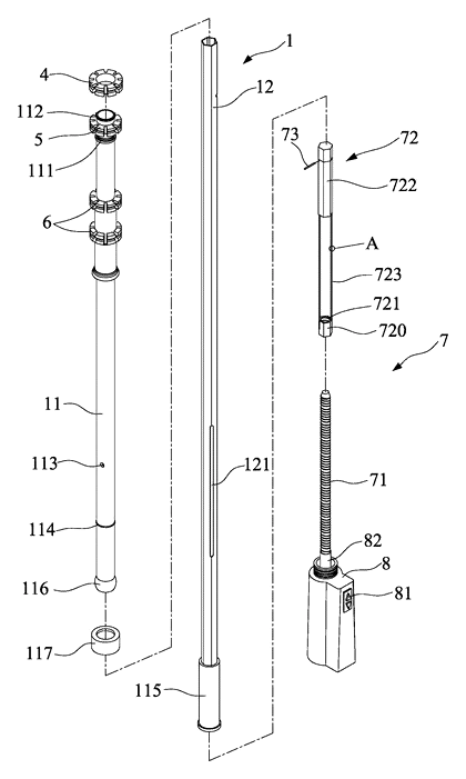
| 1 | Middle rod group | Contains the middle pipe (12) and movable outer tube (11). |
| 2 | Umbrella frame | Includes main skeletons (21), reflexed frame (22), traction fulcra (23), long branched bones (24), and short fulcra (25). |
| 3 | Umbrella cloth | Outer umbrella cloth (31) and inner umbrella cloth (32) fixed on the frame. |
| 4, 5, 6 | Upper, middle, lower nests | Pivot points connecting the frame to the rod group. |
| 7 | Automatic open-close driving structure | Screw mandrel (71), ejector sleeve (72), and power source. |
| 8 | Umbrella handle | Houses the power source and the control button (81). |
| 9 | Cushion pad | Prevents excessive impact between the lower nest and middle nest. |
| 111 | Position limiting structure | Applies upward force to the middle nest during closing. |
| 114 | Convex annular wall | Assists the lower nest during deployment. |
Operating steps
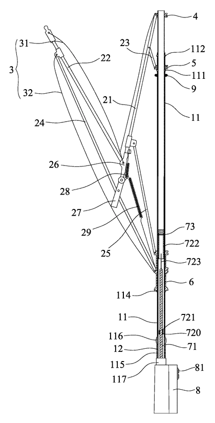
- Opening: The user presses the button (81) on the umbrella handle. The power source drives the screw mandrel (71) forward. The nut portion (721) of the ejector sleeve moves up the mandrel, pushing the connecting portion (722) and supporting part (723) to lift the outer tube (11) relative to the middle pipe (12).
- The position limiting structure (111) on top of the outer tube pushes the middle nest (5) upward. This action uses the traction fulcra (23) to push the main umbrella skeletons (21) open.
- Simultaneously, the contraction spring (28) and traction piece (27) affect the long branched bone (24), short fulcra (25), and reflexed umbrella frame (22) to deploy outward. The lower nest (6) moves to the top of the outer tube, locked by the umbrella closing spring (29).
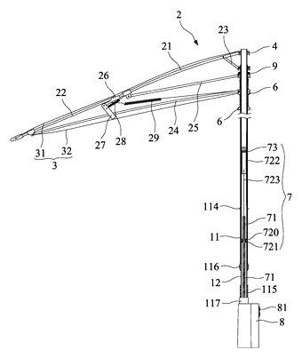
- Closing: Pressing the button again starts the power source in reverse. The screw mandrel rotates backward, moving the nut portion down. The supporting part pulls the outer tube down relative to the middle pipe.
- The position limiting structure releases the upward force on the middle nest. Under the umbrella closing spring, the main skeletons push down the traction fulcra, causing the middle nest to move down. The long branched bones lose tension, allowing the lower nest to slide down. The reflexed frame folds inward, and the outer cloth’s rain face encloses inside the inner cloth.
Applications
Commuting and public transit
Commuters boarding buses or trains often struggle to close wet umbrellas quickly in crowded aisles. This reverse-folding umbrella closes automatically at the press of a button, folding the wet surface inward so it does not drip on fellow passengers or the commuter’s own clothing.
Entering and exiting vehicles
Drivers and passengers need to transition between a car interior and the rain without soaking the seats. Because the canopy folds in reverse toward the handle, the user can close the umbrella while still partially seated, trapping the water inside the fabric layers before bringing it into the cabin.
Carrying groceries or luggage
Shoppers or travelers holding bags cannot easily use both hands to wrestle a manual umbrella closed. The motorized screw-drive mechanism allows one-handed operation via the handle button, freeing the other hand to manage packages or rolling luggage.
Corporate events and trade shows
Brands distributing promotional items want products that demonstrate clear mechanical differentiation. A motorized, reverse-closing umbrella serves as a functional item that recipients will use repeatedly, providing ongoing visibility for the brand logo printed on the canopy.
Where it is less suitable
- Extreme wind conditions - complex articulated frames with long branched bones and reflexed structures may be more susceptible to inversion in gale-force winds compared to heavy-duty storm umbrellas.
- Ultra-lightweight backpacking - the motor, battery, and screw mandrel add weight to the handle, making it less ideal for hikers prioritizing minimal pack weight.
- Areas without charging access - since the power source requires energy, users who cannot recharge the handle battery regularly will find manual umbrellas more reliable.
Frequently asked questions
How does the umbrella open and close automatically?
A power source inside the handle drives a screw mandrel. When the button is pressed, the mandrel rotates, moving an ejector sleeve up or down. This sleeve pushes or pulls an outer tube along the middle pipe, which in turn forces the frame pivots to deploy or collapse the canopy without manual pulling.
What happens to the wet side of the umbrella when it closes?
The frame folds in reverse, collapsing inward toward the handle rather than outward. According to the patent, this motion traps the rain-facing side of the outer umbrella cloth inside the canopy. If the double-layer cloth configuration is used, the inner umbrella cloth covers the wet outer cloth, preventing water from dripping onto clothing or car seats.
Is the canopy single or double layer?
The patent describes both options. Claim 7 specifies a double-layer setup with an outer umbrella cloth covering the main skeletons and reflexed frame, and an inner umbrella cloth covering the long branched bones. The description notes it is not limited to this and can be a single-layer structure where the rain face still folds inward.
Does the motor make a lot of noise?
The patent addresses noise reduction. Claims 4 and 5 describe using rigid wire bodies as the supporting part for the ejector sleeve, which can be wrapped in a sound-absorbing layer, such as a rubber sleeve or soft casing, to prevent collision noise against the middle pipe during the reset movement.
How is the umbrella powered?
The handle contains a power source that provides forward and reverse driving. Claim 9 states this can be a machine drive or a rotating motor operated through a change-speed gearing group. Specific battery types and capacities are set in design / confirmed on prototypes.
What sizes are available?
The patent text does not specify canopy diameters or overall lengths. Exact dimensions for the middle pipe, outer tube, and canopy spread are to be confirmed in design based on the buyer’s target market requirements.
Can this design be made and sold in the US?
This patent was filed only in China and is in force there until at most 2027-01-09 (if annual fees are paid). It does not restrict manufacturing or selling in the United States. However, because automatic and reverse-folding umbrellas are widely patented globally, we recommend a freedom-to-operate check before volume production.
Are you affiliated with the patent owner?
No. IP2M is an independent design and manufacturing service working from the public patent document.
Request a quote
Click Request a Quote below to see our email address - copy it, or open your email app with a ready-made message. Please mention patent CN206462545U in the subject.
Helpful details to include:
- Your company and channel (promotional distributor, automotive accessory brand, retail buyer, outdoor wholesaler)
- Target canopy size and preferred cloth configuration (single or double layer)
- Handle requirements (motor type, expected battery life per charge)
- Color and branding specifications for the canopy and handle
- Estimated quantity and target price
- Timeline - when you would like samples and the first shipment
You can also reach us at (332) 203-9997.
Explore this product
Interested in building this?
Tell us your target market, quantity and timeline. We reply with options for prototyping, small-batch runs or volume production.
Send your inquiry to
Please put CN206462545U in the subject line and tell us your company, country, estimated quantity and timeline.
Prefer to talk? Call (332) 203-9997.
More product-ready patents
All Apparel & Accessories patents →
Apparel & Accessories
Stacked Zipper with Teeth That Mesh Top-to-Bottom
Zipper whose two identical tooth rows mesh on top of each other, closed by a simplified slider.
Patent CN205795062U
Apparel & Accessories
Impact-Resistant Glove with a 3D-Printed Lattice Layer
Work glove with a 3D-printed lattice impact layer, TPU knuckle guards and a light mounting area.
Patent CN213785583U
Apparel & Accessories
Massage Insole with Spring-Back Silicone Nubs and a Removable Top Layer
Layered insole: silicone nubs rise through a removable perforated top sheet and sink under each step.
Patent CN208286505U
Apparel & Accessories
Heel-Less Carbon Plate Running Shoe Sole for Forefoot Strikers
Running sole for forefoot strikers: no ground-touching heel, winged carbon plate between two midsoles.
Patent CN216723354U
Apparel & Accessories
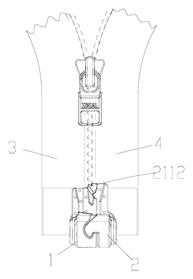
Waterproof Magnetic Zipper Stop That Snaps the Two Halves Together
Separating-zipper stop with sealed magnets: pin and box snap together one-handed, safe in rain and wash.
Patent CN215075936U
Apparel & Accessories
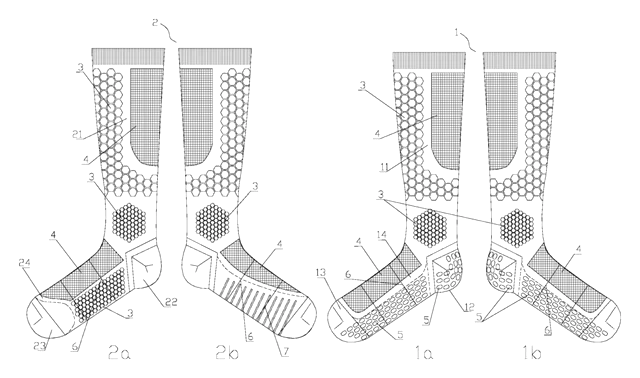
Left-Right Specific Soccer Socks: Grip for the Plant Foot, Touch Pads for the Kicking Foot
Soccer socks knitted as a left-right pair: grip zones for the plant foot, pads for the kicking foot.
Patent CN212728807U
Browse by category
- Apparel & Accessories (22)
- Baby & Kids (16)
- Bags & Luggage (9)
- Bath & Personal Care (16)
- Car Accessories (10)
- Furniture, Bedding & Storage (12)
- Garden & Outdoor (18)
- Health & Wellness (8)
- Home, Kitchen & Cleaning (24)
- Lighting (12)
- Packaging & Containers (6)
- Pet Products (6)
- Phone & Camera Accessories (4)
- Retail Display (13)
- School, Office & Art (19)
- Sports & Recreation (25)
- Tools & Workshop (27)
- Toys & Games (12)
This page is based on the public patent document CN206462545U, assigned to XIAMEN MINGHE INDUSTRIAL Co Ltd. IP2M is an independent manufacturing service and is not affiliated with, endorsed by or licensed by the patent owner. Images marked as concept renderings are illustrations, not photos of an existing product. Patent status information is provided for reference only and is not legal advice; confirm freedom to operate for your market before production. Full disclaimer.