
Patent CN206499205U
Updated November 6, 2026Seat Foot Frame with Removable Snap-Lock Legs
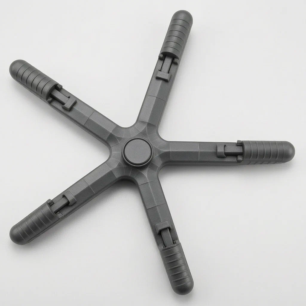
Traditional star bases require screws or permanent welding, making shipping bulky and repairs difficult. This design splits the legs into fixed arms extending from the central hub and removable outer segments. The outer segment snaps in place using a two-stage mechanical lock: a cylindrical pin seats between support blocks, and a curved tab drops into a locking neck. A locating piece rests against catches to prevent accidental release. To remove the leg, upward pressure pivots the tab out of the neck, releasing the pin. This structure supports easy flat-pack shipping for office chairs and simple caster replacement for end users.
- China utility model - lapsed
- No filings outside China
- Office chair bases
- Snap-fit leg connections
Splat! What let you down?
🔗
Snap-Fit Interface
Movable legs lock onto fixed arms using a cylindrical pin and neck groove, requiring no tools.
📦
Flat-Pack Friendly
Separating legs from the central hub reduces packing volume and simplifies logistics.
🔄
Quick Replacement
Legs can be detached by pivoting the locking tab, allowing easy repair or modification.
⚙️
Integrated Reinforcement
The central sleeve and disc are strengthened by evenly distributed ribs for load stability.
Bring this product to market
- ✓ Patent review Patent family and legal status reviewed in the relevant jurisdictions.
- 2 Product brief · now How it works, uses and options written up
- 3 Prototype First samples for buyers to review
- 4 Pilot run Small first batch for launch customers
- 5 Volume production Repeat orders at scale
Buyer interest
– of 100 buyers needed to start prototyping
One click, no sign-up. Each vote is one real visitor, and products with the most interest go to prototyping first.
Build team: no members yet. Need a partner, co-funding or skills to build this? Join and we introduce the team once it forms.
Patent Rights & Team Participation
Before joining a development team, participants should ensure they have the necessary rights or authorization to participate in the project.
Participation is generally appropriate where:
- You own the relevant patent rights or have obtained permission or a license from the rights holder.
- The relevant patent rights have expired or have been legally invalidated in the jurisdictions where the planned activities will take place.
- The planned development, manufacturing, and commercialization activities have been independently assessed and do not infringe applicable patent rights in the relevant jurisdictions.
Important: Being located outside a country where a patent is protected does not automatically exempt you from patent infringement risks. Patent rights may apply based on where development, manufacturing, use, sale, or import activities take place.
IP2M does not grant any patent license or authorization through team participation. Joining a project does not provide permission to use, manufacture, or commercialize patented technology.
The problem
Standard office chair bases typically consist of a single molded or cast five-star shape. While robust, this design creates challenges for modern retail and e-commerce. Shipping fully assembled bases increases package volume, raising freight costs. Additionally, if a leg breaks or a caster needs upgrading, replacing the entire base is often necessary because the legs cannot be separated from the central hub. Some modular designs exist but rely on screw threads or complex clips that require tools for installation, slowing down assembly lines and frustrating end-users who want quick customization. There is a need for a base that maintains structural integrity under load while allowing tool-free attachment and detachment of individual leg segments.
The solution
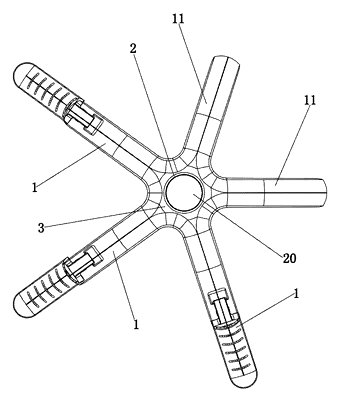
This patent describes a seat foot frame divided into a central support base and multiple legs extending radially outward. Each leg comprises two parts: a fixed leg permanently connected to the base and a movable supporting leg that attaches to the tip of the fixed leg.
The connection uses a specific interface arrangement:
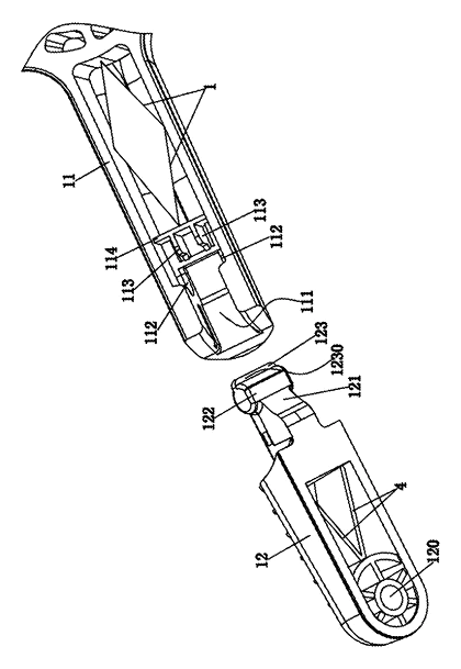
- The fixed leg features a deck with two support blocks forming a gap, known as a neck.
- The movable leg has a connector consisting of a cylindrical fixture block and a briquetting (locking tab).
- During assembly, the cylindrical block is pressed between the support blocks, and the tab is pulled down until it snaps into the neck.
- A locating piece on the connector rests against parallel catches on the fixed leg to secure the position.
Who it is for
- E-commerce furniture brands looking to reduce shipping dimensions and weight for their chair SKUs.
- Office furniture manufacturers needing faster assembly times on production lines without manual screwing.
- Replacement part suppliers who can sell individual leg tips or casters without bundling full bases.
- DIY consumers who prefer tool-free upgrades or repairs for their existing seating.
How it works
The main parts
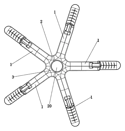
| No. | Part | What it does |
|---|---|---|
| 1 | Leg | Radial arm extending from the center. |
| 11 | Fixed leg | Inner section integrated with the base disc. |
| 12 | Movable supporting leg | Outer section that snaps onto the fixed leg. |
| 111 | Neck | Gap in the fixed leg deck where the tab locks. |
| 112 | Support blocks | Two protrusions holding the cylindrical pin. |
| 121 | Briquetting | Tab on the movable leg that drops into the neck. |
| 122 | Cylindrical fixture block | Pin that seats between support blocks. |
| 123 | Locating piece | Rests against catches to prevent back-out. |
| 2 | Sleeve pipe | Central tube receiving the gas lift cylinder. |
| 3 | Fixed disc | Plate connecting the sleeve to the legs. |
| 4 | Reinforcement | Ribs strengthening the space between sleeve and disc. |
Assembly and Disassembly Steps
- Align: Position the movable leg so the cylindrical fixture block faces the support blocks on the fixed leg.
- Insert: Press the block between the support blocks. The stepped ramp on the locating piece aids entry.
- Lock: Pull the movable leg downward. The briquetting tab slides into the neck groove until it clicks past the catches.
- Secure: The locating piece rests against the catches, preventing the tab from lifting accidentally.
- Remove: Apply upward pressure to the outer end of the movable leg. The neck acts as a fulcrum, lifting the tab out of the groove and releasing the cylindrical block.
Applications
Flat-Pack Office Chairs
Brands selling online can ship the central base separately from the leg tips. This significantly reduces box size, lowering shipping costs per unit. End-users simply snap the legs on, avoiding the need for Allen keys or screwdrivers during initial setup.
Customizable Seating Solutions
Wholesalers can offer different leg finishes or lengths using the same central hub. If a customer wants longer legs for a higher desk setting, they swap only the movable tips rather than buying a new base. This flexibility appeals to ergonomic specialists and boutique furniture retailers.
Rapid Repair Services
In corporate environments, damaged chair legs are common due to rolling over obstacles. Facility managers can replace just the damaged leg instead of replacing the whole base. This minimizes downtime compared to unscrewing an entire base from the gas cylinder, which often seizes over time.
Retail Display Units
Showroom models frequently suffer from wear or breakage. Staff can instantly replace a snapped leg tip to maintain display aesthetics. The tool-free nature ensures that displays remain functional even when maintenance staff are not equipped with specialized tools.
Where it is less suitable
- Heavy-Duty Industrial Stools: High-load applications may require solid cast bases without joints, as snap-fits might have lower fatigue resistance than continuous metal structures.
- Extreme Temperature Environments: Plastic components in the snap interface could become brittle or deform under extreme heat or cold, affecting the lock’s security.
- Vibration-Prone Settings: In areas with constant heavy vibration, the locating piece must be robust enough to prevent accidental unlocking, though the patent includes catches for this purpose.
Patent & Production
At a glance
| Patent number | CN206499205U (application CN201621357058) |
| Type | China utility model (实用新型) - protects product shape and structure |
| Original title | Seat foot frame (座椅脚架) |
| Patent owner | Individual |
| Inventors | Qin Sanguang |
| Filing date | 2016-12-12 |
| Grant date | 2017-09-19 |
| Status (China) | Lapsed - terminated for non-payment of annual fees (recorded 2024-07-02) |
| Patent family | Public record shows Chinese filings only - no US, European, Japanese, PCT or other filings listed |
| Cited by | 9 later documents |
| Source | Google Patents (search for CN206499205U) |
What the claims cover, in plain language
Claim 1 - a seat foot frame with a central support base and radially extending legs. Each leg includes a fixed leg integrated with the base and a movable supporting leg removably connected via an interface. The interface features a deck on the fixed leg with a neck, and a snap fit connector on the movable leg. The connector has a cylindrical fixture block and a briquetting (tab) that locks into the neck.
Claim 2 - the deck includes two support blocks forming the neck. The movable leg’s connector has a cylindrical block that presses between these supports, and a tab that cards into the neck.
Claim 3 - the deck includes two parallel catches on the bottom wall. The connector includes a locating piece that withstands these catches to secure the lock.
Claim 4 - the locating piece has a stepped ramp type breach at the junction with the cylindrical block to aid insertion.
Claim 5 - the deck includes fixed plates on the inner walls, to which the catches are connected.
Claim 6 - the fixed leg and movable supporting leg are reinforced by a reinforcement element (likely a rib or bracket depending on material).
Claim 7 - the outer end of the movable supporting leg has a mounting hole for installing a roller (caster).
Claim 8 - the frame can have 1-5 legs, with 1 or 2 being movable supporting legs.
Claim 9 - the support base includes a central sleeve pipe and a fixed disc; the axis hole is in the sleeve, and legs connect to the disc periphery.
Claim 10 - reinforcements are evenly distributed in the annular space between the sleeve pipe and fixed disc.
This is a simplified reading for orientation only. The legal scope is defined by the exact claim wording in the official Chinese document.
What this means for US production
This patent was filed in China and has lapsed due to non-payment of fees, so it no longer restricts anyone in China either. The public record shows no US or other foreign counterpart.
Two points to settle early:
- Other patents may exist. Chair bases are a competitive field. Companies like Henglin Home Furnishing Co., Ltd. and Zhejiang Yuyue Furniture Co., Ltd. have cited this patent in subsequent international filings (WO2020233411A1 and WO2021012988A1 respectively), indicating active innovation in this area. A freedom-to-operate (FTO) review is recommended to ensure no newer US patents cover similar snap-fit mechanisms.
- Load standards. US buyers expect BIFMA certification. The snap joint must pass rigorous static and dynamic load tests required by ANSI/BIFMA X5.1.
Customization and manufacturing
What can be customized
| Area | Options |
|---|---|
| Material | Nylon, PP, or aluminum alloy for base and legs |
| Leg Count | 3, 4, or 5 legs (patent specifies 1-5) |
| Finish | Powder coating, chrome plating, or textured plastic |
| Caster Mount | Standard stem diameter or universal fit inserts |
| Color | Black, white, grey, or custom brand colors |
Things to plan for (US market)
- ANSI/BIFMA X5.1 - General Use Lounge Chairs standard. Requires testing for durability, strength, and safety. The snap-fit joint is a critical failure point to test.
- Prop 65 - If using recycled plastics or certain metal finishes, California warning labels may be required.
- Recyclability - Many US buyers prefer mono-material designs (all nylon) for easier recycling versus mixed metal/plastic assemblies.
How a project runs
- Inquiry - Material choice, leg count, and target price.
- Design - Mold flow analysis for the snap-fit geometry to ensure proper retention force.
- Prototype - 3D printed or soft-tool samples for fit checks.
- Pilot run - Load testing and cycle testing (attach/detach 100+ times).
- Production - Injection molding, painting/finishing, assembly.
Quantities & timeline
Injection molds for the central hub and each leg component are the primary tooling cost. Cycle time depends on part thickness. Send us your material preference, leg configuration, finish, quantity and target price and we will reply with options.
Production notes
Tooling and process
Injection molding is likely the primary process for the base and legs if using plastic. Steel tube bending and welding might apply if the fixed leg is metal, but the patent suggests an integrated structure, favoring molded parts. Press-fit assembly is used for attaching casters.
Cost drivers
Connector and bracket count typically affects mold complexity. Tube diameter and wall thickness influence material usage and cooling time. Surface finish requirements (e.g., high-gloss vs. matte) drive secondary processing costs. Packaging volume is reduced by the split-leg design, offsetting some tooling costs.
Prototyping path
Typically, start with a 3D model and load path check to verify snap-fit tolerances. Produce welded or bolted frame samples if hybrid materials are chosen. Use 3D-printed connectors for initial fit testing before cutting steel molds. Conduct load tests on the frame to validate the neck-and-tab mechanism.
What we would change before tooling
We would likely adjust the draft angles on the neck and briquetting to ensure consistent molding. Verifying the interference fit of the cylindrical block against support blocks is critical to prevent loosening after repeated load cycles.
Common failure points
Loose joints after repeated load are the main risk if the snap tolerance is too wide. Insufficient load rating could occur if the neck wall thickness is inadequate. Tipping under uneven load depends on the base radius, not the joint itself. Stripped screws are avoided by using snap-fits, but coating chips at edges may appear if painted parts rub during assembly.
Patent drawings
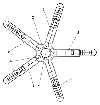
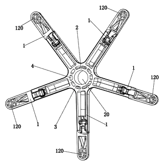
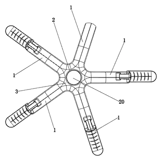
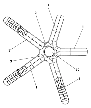
Drawings reproduced from the public patent document for reference.
Frequently asked questions
How do you attach the legs?
You align the cylindrical pin on the leg tip with the gap in the base arm, press it in, and pull the leg down until the tab snaps into the locking groove. No tools are required.
Is the connection strong enough for daily use?
The design uses a mechanical interlock (pin and tab) supported by catches. While the patent doesn’t specify load ratings, such snap-fit bases are typically engineered to meet standard office chair loads (around 250-300 lbs) when made from reinforced nylon or metal.
Can I replace just one broken leg?
Yes. Since the legs are separate components, you can detach and replace a single leg tip without changing the entire base. This is useful for repairs or swapping caster types.
Does it work with all casters?
The movable leg has a mounting hole designed for standard casters. You can likely use universal stem casters or specific inserts depending on the final hole diameter chosen in production.
What materials are available?
The patent mentions reinforcement ribs, suggesting injection-molded plastics (like nylon or PP) or die-cast aluminum. Metal versions would likely use steel or aluminum extrusion processes.
Why choose this over a solid base?
It offers better packaging efficiency for shipping and easier maintenance. For manufacturers, it allows modular inventory management—stocking hubs and leg tips separately.
Can this design be made and sold in the US?
The patent was filed in China and has lapsed, and the public record shows no US counterpart, so it does not restrict the design in the US or in China. However, chair bases are a heavily patented field, so we recommend a freedom-to-operate check to ensure no newer US patents cover similar snap-fit mechanisms.
Are you affiliated with the patent owner?
No. IP2M is an independent design and manufacturing service working from the public patent document.
Request a quote
Click Request a Quote below to see our email address - copy it, or open your email app with a ready-made message. Please mention patent CN206499205U in the subject.
Helpful details to include:
- Your company and channel (office furniture brand, e-commerce seller, hardware supplier)
- Material preference (nylon, aluminum, steel)
- Leg configuration (3, 4, or 5 legs)
- Finish (color, texture, coating)
- Estimated quantity and target price
- Timeline - when you would like samples and the first shipment
You can also reach us at (332) 203-9997.
Page editor: Daniel Chen, Product Research Editor · IP2M
Last updated November 6, 2026. If something on this page looks wrong, email [email protected] and we will check it against the patent.
Interested in building this?
Tell us your target market, quantity and timeline. We reply with options for prototyping, small-batch runs or volume production.
Send your inquiry to
Please put CN206499205U in the subject line and tell us your company, country, estimated quantity and timeline.
Prefer to talk? Call (332) 203-9997.
More product-ready patents
All Furniture, Bedding & Storage patents →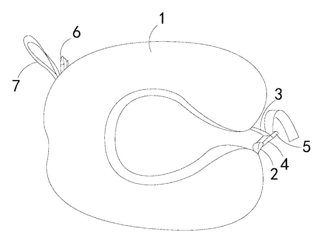
Furniture, Bedding & Storage
Roll-Up Travel Neck Pillow with Buckles
U-shaped travel pillow with a front buckle and a back buckle that holds it rolled up for carrying.
Patent CN206543091U
Furniture, Bedding & Storage
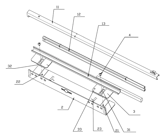
Width-Adjustable Slide Rail for Pull-Out Baskets
Basket slide rail on a slotted, scaled adjusting plate, so one pull-out basket fits several cabinet widths.
Patent CN208909382U
Furniture, Bedding & Storage
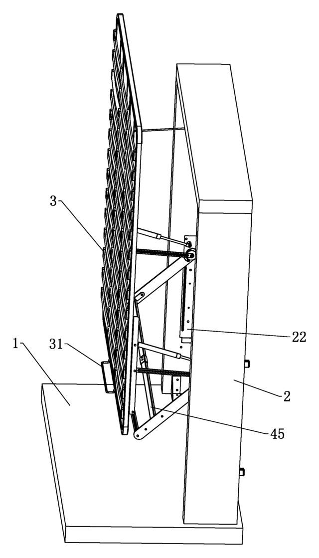
Lift-Up Storage Bed with Four-Bar Linkage That Slides the Deck Away from the Headboard
Storage bed deck that rises on four-bar linkages and gas springs, clearing the headboard as it opens.
Patent CN210870645U
Furniture, Bedding & Storage
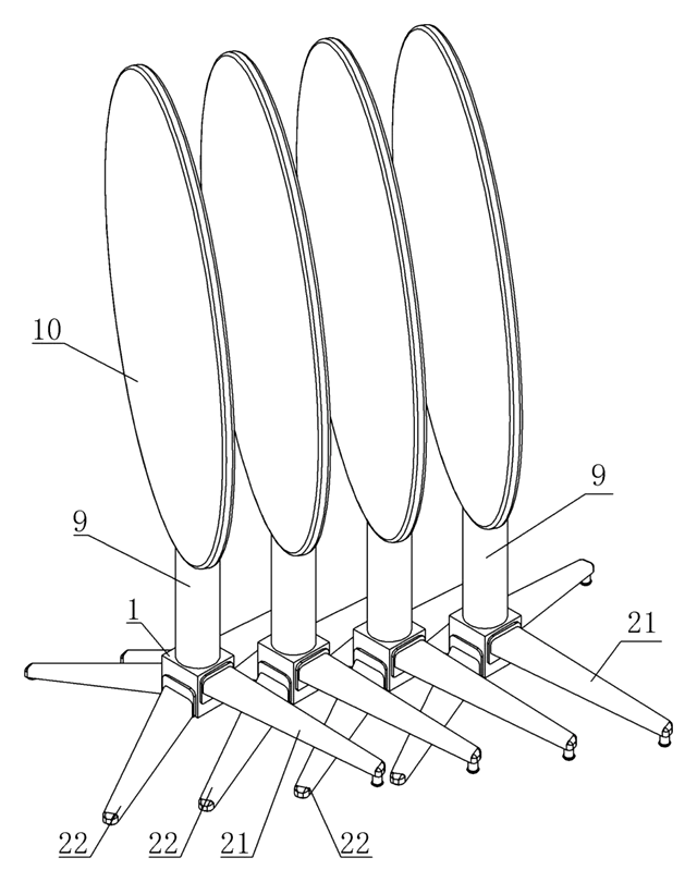
Self-Leveling, Nesting Table Base with a Torsion-Ring Leg Hub
Four-leg base that self-levels through a torsion-ring hub and nests sideways with flip-top tables.
Patent CN211483640U
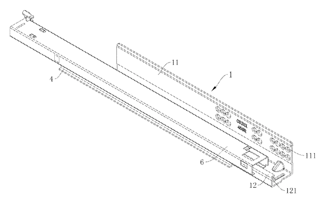
Furniture, Bedding & Storage
Rack-and-Pinion Synchronized Drawer Slide with a Folded-In Fixed Rail
Full-extension drawer slide: a pinion between two racks keeps the rails moving in step.
Patent CN206314843U
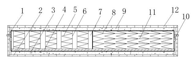
Furniture & Bedding
Dual-Zone Split-Spring Mattress with Removable Fabric Cover
Half-pocket, half-standard spring mattress sharing one base plate, with a removable cover.
Patent CN208355064U
Browse by category
- Apparel & Accessories (44)
- Baby & Kids (28)
- Bags & Luggage (16)
- Bath & Personal Care (29)
- Car Accessories (23)
- Furniture, Bedding & Storage (23)
- Garden & Outdoor (31)
- Health & Wellness (13)
- Home, Kitchen & Cleaning (47)
- Lighting (22)
- Packaging & Containers (11)
- Pet Products (11)
- Phone & Camera Accessories (9)
- Retail Display (24)
- School, Office & Art (33)
- Sports & Recreation (43)
- Tools & Workshop (51)
- Toys & Games (21)
This page is based on the public patent document CN206499205U, assigned to Individual. IP2M is an independent manufacturing service and is not affiliated with, endorsed by or licensed by the patent owner. Images marked as concept renderings are illustrations, not photos of an existing product. Patent status information is provided for reference only and is not legal advice; confirm freedom to operate for your market before production. Full disclaimer.