
Patent CN206652176U
Updated October 26, 2026Sensor-Enabled Training Running Shoe with Laser Stride Guide
Most wearable running trackers sit on the wrist or clip to the laces, measuring steps but missing what happens under the foot. This design builds the sensors directly into the sole and adds a visible laser line on the ground ahead of the runner. Four corner pressure sensors map exactly how the foot lands, while the projected guide line gives an instant visual target for stride length without looking down at a screen. The result is a self-contained coaching tool built into the footwear itself.
- China utility model - lapsed
- No filings outside China
- Footwear & sports electronics
- Sole sensors, laser guide, IMU, GPS and Bluetooth
Splat! What let you down?
👟
Four-point pressure mapping
Sensors at each corner of the sole detect left/right forefoot and heel strike forces independently.
🔦
Laser stride guide
A toe-mounted laser projects a visible line on the ground so runners can match a target stride length.
📡
Full motion capture
Three-axis accelerometer, gyroscope and magnetometer combine to reconstruct the foot's movement path.
💤
Auto sleep sensor
An infrared detector senses when the shoe is taken off and shuts down the circuit to preserve battery life.
Bring this product to market
- ✓ Patent vetted China-only family and legal status checked
- 2 Product brief · now How it works, uses and options written up
- 3 Prototype First samples for buyers to review
- 4 Pilot run Small first batch for launch customers
- 5 Volume production Repeat orders at scale
Buyer interest
– of 100 buyers needed to start prototyping
One click, no sign-up. Each vote is one real visitor, and products with the most interest go to prototyping first.
Build team: no members yet. Need a partner, co-funding or skills to build this? Join and we introduce the team once it forms.
The problem
Runners trying to improve their form often rely on wrist-worn watches or phone apps that estimate pace and distance but cannot feel how the foot actually strikes the ground. Cadence and stride length are usually reviewed after a run on a screen, making it hard to correct posture mid-stride. According to the patent, the goal is a shoe that records comprehensive running data—cadence, stride, posture, route and foot-strike force—and simultaneously guides the runner in real time through visual and audible cues.
The solution
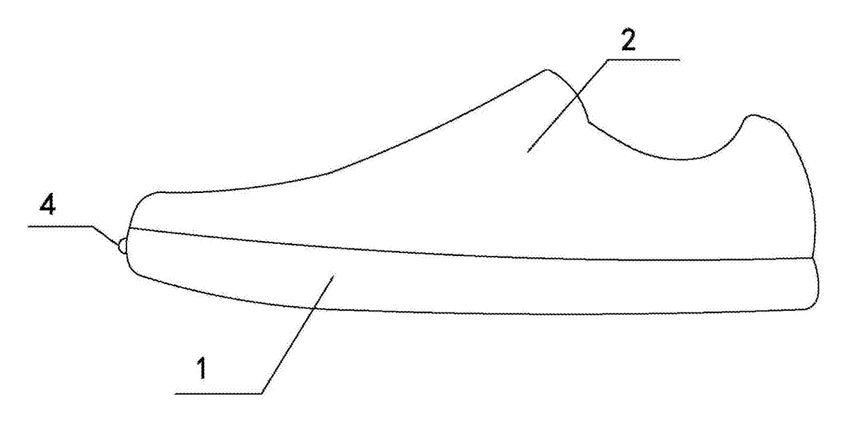
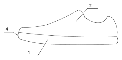
- The shoe consists of a sole (1) and a vamp (2) fixed together.
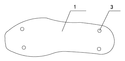
- Inside the sole, four pressure sensors (3) are placed at the left-front, right-front, left-rear and right-rear corners to measure landing force distribution across the foot.
- At the front of the sole, a guiding laser emitter (4) is mounted on a spherical universal adjuster (a hollow ball cover with a damping ball center) so the beam angle can be aimed manually. It projects a straight guide line onto the ground ahead of the runner to set a visual stride-length target.
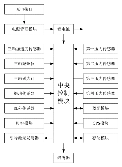
- An internal control circuit houses a central control module connected to a three-axis accelerometer, three-axis gyroscope, three-axis magnetometer, vibration sensor, clock module, memory module, GPS module, Bluetooth module, buzzer and infrared sensor.
- The accelerometer, gyroscope and magnetometer work together to determine the foot’s acceleration, angular velocity and orientation, allowing the system to reconstruct the running trajectory. The vibration sensor triggers on each footfall to calculate cadence alongside the clock module.
- The buzzer emits rhythmic tones to pace the runner’s cadence audibly. The infrared sensor detects whether the shoe is being worn; when removed, it signals the central module to enter a power-saving rest state.
- A lithium battery with a power management module and charging port supplies energy to all components.
Who it is for
- Athletic footwear brands looking to integrate hardware-based coaching features directly into a running shoe rather than relying solely on companion apps.
- Sports academies and university track programs that need objective foot-strike data from multiple athletes during practice sessions without attaching external pods.
- Physical therapy clinics focused on gait retraining, where therapists require precise pressure maps of the forefoot and heel during walking or jogging drills.
- Consumer electronics companies exploring smart footwear as a product category, using this architecture as a reference platform for sensor integration.
How it works
The main parts
| No. | Part | What it does |
|---|---|---|
| 1 | Sole | Houses the sensors, battery and circuit; forms the base of the shoe. |
| 2 | Vamp | Upper part of the shoe, fixedly mounted on the sole. |
| 3 | Pressure sensors | Four units at the sole corners detecting forefoot and heel strike forces. |
| 4 | Guiding laser emitter | Projects a visible line on the ground for stride guidance; mounted on a ball-and-socket adjuster. |
| - | Central control module | Microcontroller processing all sensor inputs and driving outputs. |
| - | IMU (accelerometer, gyroscope, magnetometer) | Captures linear acceleration, rotation and magnetic heading to map foot motion. |
| - | Vibration sensor & clock module | Detects footfall impacts and timestamps them to compute cadence. |
| - | GPS module | Records the outdoor running route in real time. |
| - | Bluetooth module | Transfers stored data wirelessly to a phone, tablet or computer. |
| - | Buzzer | Emits rhythmic audio beats for cadence pacing. |
| - | Infrared sensor | Detects presence of the foot inside the shoe to trigger auto-sleep. |
| - | Power module | Lithium battery, power management IC and external charging port. |
| - | Memory module | Stores sensor logs locally before wireless transfer. |
Using the shoe
- Put on the shoe - the infrared sensor detects the foot and wakes the central control module from its power-saving state.
- Aim the laser - rotate the ball center inside the spherical universal adjuster until the projected line sits at the desired distance ahead of the toe. Damping friction holds the position.
- Start running - the four pressure sensors record left/right forefoot and heel loads on every step. The vibration sensor registers each impact.
- Follow the cues - keep your foot landing on or near the projected laser line to maintain the target stride length; match your steps to the buzzer’s rhythm to hold a steady cadence.
- Review the data - after the run, the Bluetooth module syncs the memory module’s logs (pressure maps, IMU trajectory, GPS route, cadence counts) to a paired device for analysis.
- Take off the shoe - the infrared sensor no longer detects the foot, and the central module powers down the active circuits automatically.
Applications
Track and field sprint training
Sprinters working on stride length consistency can use the laser line as a physical marker on the track surface. Instead of relying on a coach shouting distances, the athlete sees exactly where the next footfall should land. The four corner pressure sensors confirm whether the drive phase is generating symmetrical force through the forefoot.
Distance running cadence drills
Marathon and half-marathon runners often aim for a specific step rate to improve efficiency. The onboard buzzer provides a continuous metronome beat independent of headphones or phone speakers. Because the vibration sensor triggers directly from foot impact, the cadence reading reflects actual ground contacts rather than arm swings measured by a wrist watch.
Gait rehabilitation in clinical settings
Physical therapists treating patients recovering from lower-limb injuries need precise weight-bearing data. The separated left-front, right-front, left-rear and right-rear sensors show exactly which quadrant of the foot is accepting load during walking or light jogging. Therapists can download the logs via Bluetooth after a treadmill session to track symmetry improvements over weeks.
University sports science research
Kinesiology departments studying biomechanics benefit from having acceleration, gyroscopic and magnetometer data captured simultaneously with plantar pressure. The combined IMU data allows researchers to reconstruct the three-dimensional path of the foot through the gait cycle. Local storage ensures no data packets are dropped due to wireless interference during lab trials.
Youth athletic development programs
Young runners learning proper form may not yet use smartphones during practice. The self-contained laser guide and buzzer give immediate feedback without requiring a screen. Coaches can set the laser distance to match age-appropriate stride targets, letting the athletes focus purely on matching the visual and audio cues.
Where it is less suitable
- Casual daily walking - the laser guide and high-frequency sensor polling consume battery faster than basic step counters, making it excessive for general lifestyle tracking.
- Trail running on uneven terrain - projecting a flat laser line onto rocks, roots or mud is impractical, and the rigid sensor housing inside the sole may limit natural flex on technical surfaces.
- Wet weather racing - while the sole encloses the electronics, competitive racing shoes prioritize minimal weight and water drainage over embedded hardware protection.
Frequently asked questions
How are the pressure sensors arranged?
The patent describes four sensors positioned at the left-front, right-front, left-rear and right-rear corners inside the sole. This layout isolates forefoot and heel strikes on both the medial and lateral sides, giving a basic map of weight distribution during the running gait cycle. Additional sensors could be added in a custom design if higher resolution is needed.
Can the runner adjust where the laser line appears?
Yes. The guiding laser emitter is mounted on a spherical universal adjuster at the front of the sole. It consists of a hollow ball cover and a rotating ball center. The runner manually pivots the emitter to change the projection distance, and the damping friction between the ball and cover holds the chosen angle in place during movement.
What powers the electronics?
A lithium battery housed within the sole powers the system. It connects to a power management module, which also interfaces with an external charging port. The exact capacity and runtime are parameters to be confirmed in design based on the chosen battery size and the power draw of the laser, IMU and Bluetooth radio.
How does the shoe know when to turn off?
An infrared sensor connected to the central control module monitors whether a foot is present inside the shoe. When the runner takes the shoe off and the sensor no longer detects the foot, the central module commands the other components to enter a resting state, reducing battery drain.
How is the running data transferred for analysis?
A Bluetooth module links the shoe’s memory to a smartphone, tablet or computer. After a session, the logged data—including pressure readings, IMU trajectories, GPS routes and cadence counts—can be synced wirelessly to the paired device for detailed review.
Will the electronics survive repeated running impacts?
The patent specifies that the sensors, battery and control circuit are embedded inside the sole. In production, these components must be encapsulated in shock-absorbing potting compounds or housed in rigid protective shells molded into the midsole foam to withstand thousands of footstrike cycles. Durability testing would be a key part of the pilot run phase.
Can this design be made and sold in the US?
The patent was filed only in China and has lapsed (terminated for non-payment of annual fees, recorded 2019-03-15), so it does not restrict the design in the US or in China. Smart footwear technologies may be covered by other US patents - see Patent & Production - so we recommend a freedom-to-operate check before volume production.
Are you affiliated with the patent owner?
No. IP2M is an independent design and manufacturing service working from the public patent document.
Request a quote
Click Request a Quote below to see our email address - copy it, or open your email app with a ready-made message. Please mention patent CN206652176U in the subject.
Helpful details to include:
- Your company and channel (athletic brand, sports tech startup, clinic supplier, distributor)
- Target user and size range (adult, youth, specific sports)
- Feature priorities (laser guide, pressure mapping, GPS, app integration)
- Estimated quantity and target price
- Timeline - when you would like samples and the first shipment
You can also reach us at (332) 203-9997.
Explore this product
Interested in building this?
Tell us your target market, quantity and timeline. We reply with options for prototyping, small-batch runs or volume production.
Send your inquiry to
Please put CN206652176U in the subject line and tell us your company, country, estimated quantity and timeline.
Prefer to talk? Call (332) 203-9997.
More product-ready patents
All Apparel & Accessories patents →
Apparel & Accessories
Stacked Zipper with Teeth That Mesh Top-to-Bottom
Zipper whose two identical tooth rows mesh on top of each other, closed by a simplified slider.
Patent CN205795062U
Apparel & Accessories
Impact-Resistant Glove with a 3D-Printed Lattice Layer
Work glove with a 3D-printed lattice impact layer, TPU knuckle guards and a light mounting area.
Patent CN213785583U
Apparel & Accessories
Massage Insole with Spring-Back Silicone Nubs and a Removable Top Layer
Layered insole: silicone nubs rise through a removable perforated top sheet and sink under each step.
Patent CN208286505U
Apparel & Accessories
Heel-Less Carbon Plate Running Shoe Sole for Forefoot Strikers
Running sole for forefoot strikers: no ground-touching heel, winged carbon plate between two midsoles.
Patent CN216723354U
Apparel & Accessories
Waterproof Magnetic Zipper Stop That Snaps the Two Halves Together
Separating-zipper stop with sealed magnets: pin and box snap together one-handed, safe in rain and wash.
Patent CN215075936U
Apparel & Accessories
Left-Right Specific Soccer Socks: Grip for the Plant Foot, Touch Pads for the Kicking Foot
Soccer socks knitted as a left-right pair: grip zones for the plant foot, pads for the kicking foot.
Patent CN212728807U
Browse by category
- Apparel & Accessories (22)
- Baby & Kids (16)
- Bags & Luggage (9)
- Bath & Personal Care (16)
- Car Accessories (10)
- Furniture, Bedding & Storage (12)
- Garden & Outdoor (18)
- Health & Wellness (8)
- Home, Kitchen & Cleaning (24)
- Lighting (12)
- Packaging & Containers (6)
- Pet Products (6)
- Phone & Camera Accessories (4)
- Retail Display (13)
- School, Office & Art (19)
- Sports & Recreation (25)
- Tools & Workshop (27)
- Toys & Games (12)
This page is based on the public patent document CN206652176U, assigned to Hunan Vocational College of Mordern Logistics. IP2M is an independent manufacturing service and is not affiliated with, endorsed by or licensed by the patent owner. Images marked as concept renderings are illustrations, not photos of an existing product. Patent status information is provided for reference only and is not legal advice; confirm freedom to operate for your market before production. Full disclaimer.