At a glance
| Patent number | CN206689990U (application CN201720375856) |
| Type | China utility model (实用新型) - protects product shape and structure |
| Original title | A kind of storage type dismantling device (一种储藏式拆装工具) |
| Patent owner | SHAOXING HUANZHOU TOOL MANUFACTURING Co Ltd |
| Inventors | Wang Boyong |
| Filing date | 2017-04-11 |
| Grant date | 2017-12-01 |
| Status (China) | Lapsed - terminated for non-payment of annual fees (recorded 2023-03-17) |
| Patent family | Chinese filings only - no US, European, Japanese, PCT or other filings listed |
| Cited by | 2 later documents |
| Source | Google Patents (search for CN206689990U) |
What the claims cover, in plain language
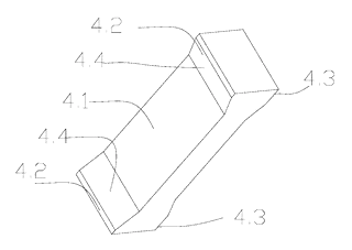
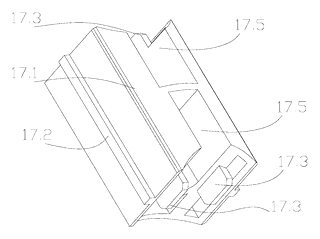
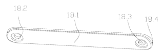
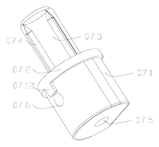
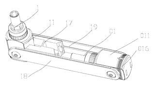
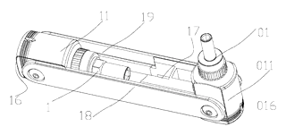
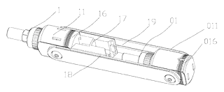
Claim 1 describes a storage-type dismantling device comprising a mounting bracket, at least one tool body rotatably installed on the bracket, and a positioning sliding block slidably mounted in the middle of the bracket. The tool body has a connecting seat with a head positioning portion and at least one side locating section. The sliding block has an end locating section that mates with either the head or side portion to lock the tool body. The bracket consists of two parallel seat boards with longitudinal slide grooves on their inner sides for the sliding block, and transverse pin-and-holes at both ends acting as hinges for the tool body.
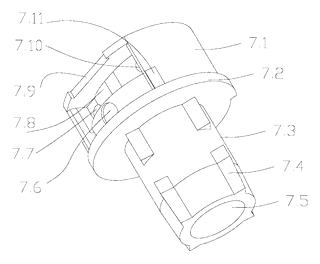
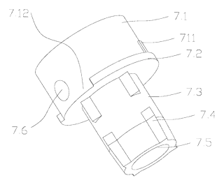
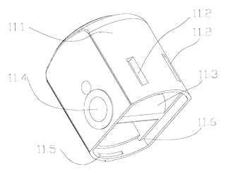
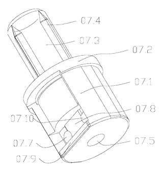
Claim 2 adds a slider containment chamber to the positioning sliding block, featuring a breach at the bottom to allow the tool body’s tail end to enter and exit the chamber. Claim 3 specifies that the mating between the sliding block and the connecting seat portions uses an interference-fit plug-socket structure. Claim 4 states the tool body includes a ratchet wheel body, with the connecting seat at its head and a tool head at its tail. Claim 5 details the connecting seat as a box and a clamping lid forming an assembly to store tool heads, with a ratchet wheel body installation portion at the box’s tail. Claim 6 lists the ratchet wheel components: a fluted disc, adjusting ring, cross-arm, spring one, spring two, ratchet shaft, stage clip (compression spring), and steel ball. It describes how the adjusting ring’s plectrum interacts with the cross-arm and how the steel ball sits between the stage clip and the adjusting ring’s locating slots. Claim 7 describes a cross-arm groove on the ratchet shaft tail for installing the cross-arm, with spring eyes at both ends for the springs.
This is a simplified reading for orientation only. The legal scope is defined by the exact claim wording in the official Chinese document.
What this means for US production
This patent was filed only in China and is lapsed (terminated for non-payment of annual fees, recorded 2023-03-17), so it no longer restricts anyone in China either. It has no US or other foreign counterpart.
Two points to settle early:
- Other patents may exist. Folding multi-tools and ratchet mechanisms are heavily patented categories, with numerous active US patents covering hinge locks, internal bit storage, and ratchet pawl designs held by major hand tool manufacturers. A freedom-to-operate (FTO) review of the sliding block lock, the connecting seat storage chamber, and the specific ratchet arrangement is needed before tooling.
- Torque rating and hinge strength. The dimensions of the hinge pins, the thickness of the mounting bracket seat boards, and the interference fit of the sliding block determine how much torque the deployed tool body can withstand before failing. These parameters must be confirmed on prototypes.
Customization and manufacturing
What can be customized
| Area | Options |
|---|---|
| Number of tool bodies | One or two, mounted at opposite ends of the bracket |
| Drive size | About 1/4-inch or 3/8-inch square drive, or hex-bit receptacle; to be confirmed in design |
| Stored tool heads | Quantity and types (hex, Torx, Phillips, slotted) sized to fit the connecting seat box |
| Materials | Carbon steel, stainless steel, or chrome vanadium for the ratchet and bracket |
| Finish | Nickel plating, black oxide, powder coating on the bracket |
| Handle grips | Overmolded TPR or plastic sleeves on the mounting bracket seat boards |
Things to plan for (US market)
- ASME B107.110 - performance standard for socket wrench handles, including ratchets; US industrial buyers often ask for proof-torque results on the ratchet and fluted disc.
- California Prop 65 - chrome plating on the ratchet parts and any PVC or rubber grip compound need a lead and phthalate check before a warning-free listing.
How a project runs
- Inquiry - define the number of tool bodies, drive sizes, stored bit types, materials, and target quantity.
- Design - engineer the mounting bracket profiles, hinge pin tolerances, sliding block geometry, and connecting seat box/lid snap fit.
- Prototype - machine samples to test the interference fit of the slider lock, the ratchet engagement, and the storage capacity.
- Pilot run - stamp and form the bracket, machine the ratchet components, mold the lids, and assemble a batch for torque and cycle testing.
- Production - progressive die stamping for the bracket, CNC machining or MIM for the ratchet internals, injection molding for the lids, finishing, and final assembly.
Quantities & timeline
The mounting bracket requires progressive stamping dies tailored to its length and profile. The ratchet internals (fluted disc, adjusting ring, ratchet shaft) demand precision machining or metal injection molds. The connecting seat box and lid require their own tooling if formed from sheet metal or molded from polymer. Torque testing of the hinge pins and sliding block lock dictates the validation phase. Send us your drive sizes, number of tool bodies, material preferences, stored bit count, quantity and target price and we will reply with options.
Patent drawings
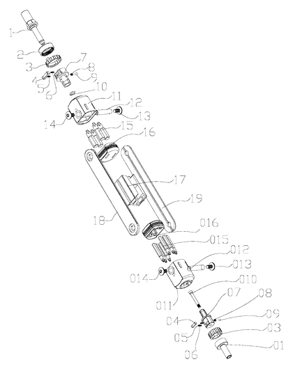
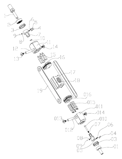
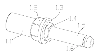
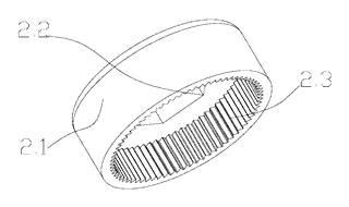
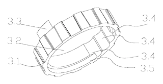
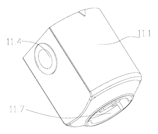
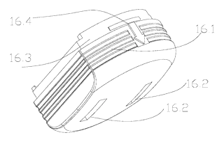
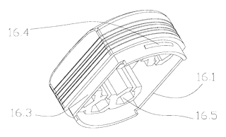
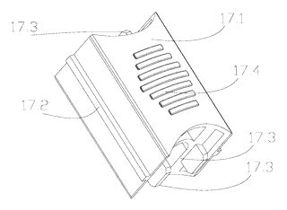
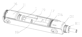
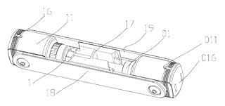
Drawings reproduced from the public patent document for reference.