At a glance
| Patent number | CN207112268U (application CN201720575337) |
| Type | China utility model (实用新型) - protects product shape and structure |
| Original title | A kind of foldable multifunctional Mobile phone clip (一种多功能折叠手机夹) |
| Patent owner | Beijing Hesse Technology Co Ltd |
| Inventors | Zhao Liang, Liu Chunlin |
| Filing date | 2017-05-23 |
| Grant date | 2018-03-16 |
| Status (China) | In force - valid until at most 2027-05-23, subject to payment of annual fees |
| Patent family | Chinese filings only - no US, European, Japanese, PCT or other filings listed |
| Cited by | 1 later document (JP6872830B1 assigned to Slick Corporation) |
| Source | Google Patents (search for CN207112268U) |
What the claims cover, in plain language
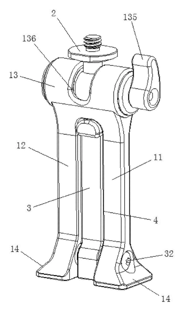
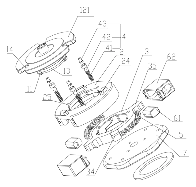
Claim 1 defines the core structure: a mobile phone clip main body with a bottom support feet mounting hole. A support foot rotates inside this hole. The foot has a longitudinal screw hole running through it and a horizontal screw hole at its end. The main body bottom has a head with holding screws and a support side.
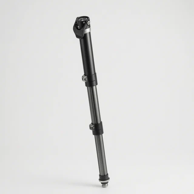
Claim 2 details the telescopic interior: lower folding legs on the main body, an expansion link inside, adjusted by a spring and nut, leading to a telescopic body with upper folding legs. A second camera screw is at the top.
Claim 3 notes the support foot end can connect to a flexible stock (selfie stick).
Claim 4 mentions a lifting rope attached to the second camera screw.
Claim 5 specifies the folding legs operate within a 0-90 degree range.
Claim 6 specifies the support foot rotates within a 0-320 degree range relative to the main body.
Claim 7 describes the support as a movable telescopic tripod.
Claim 8 confirms the screw holes are 1/4-inch size, compatible with any accessory using that standard thread.
This is a simplified reading for orientation only. The legal scope is defined by the exact claim wording in the official Chinese document.
What this means for US production
This patent was filed only in China and is currently in force in China. Making, selling, or importing this specific design within China requires permission from the patent owner. There is no direct US patent counterpart listed in the family.
Two points to settle early:
- Other patents may exist. The field of phone mounts is crowded. The patent is cited by Slick Corporation (a major tripod manufacturer), indicating they have developed related technology in Japan (JP6872830B1). A freedom-to-operate (FTO) review is essential before launching in the US, as US utility patents may cover similar rotating mechanisms or 1/4-inch integration methods.
- Mechanical durability. The rotating joint and screw threads are stress points. Material selection and tolerance control are critical to prevent stripping or breakage during repeated angle adjustments.
Customization and manufacturing
What can be customized
| Area | Options |
|---|---|
| Materials | ABS plastic, polycarbonate, aluminum alloy, stainless steel screws |
| Colors | Matte black, white, silver, custom Pantone matches |
| Clamp Width | Adjustable pads for different phone thicknesses (with/without case) |
| Rotation Resistance | Friction washers or detent clicks for the 0-320 degree foot |
| Finish | Soft-touch coating, anodized metal, glossy plastic |
| Accessories | Lanyard attachment point, cold shoe mount addition |
Things to plan for (US market)
- RoHS Compliance - Restriction of Hazardous Substances applies to electronic accessories sold in California and many other states.
- Proposition 65 - Warning labels required if materials contain listed chemicals (e.g., certain plastics or platings).
- Drop Test Standards - While no federal mandate exists, retailers often require ISTA 1A packaging testing to ensure the clip survives shipping.
- Magnetic Interference - If magnets are added for MagSafe compatibility, FCC Part 15 B unintentional radiator rules may apply if the device interacts with electronics significantly.
How a project runs
- Inquiry - Define target phone sizes, material preferences, and volume.
- Design - CAD modeling of the rotating joint and telescopic mechanism.
- Prototype - CNC machined or SLA printed samples to test rotation smoothness and clamp strength.
- Tooling - Injection molds for plastic bodies, die-casting molds for metal feet.
- Production - Assembly, quality control checks on screw threads, and packaging.
Quantities & timeline
Injection molding tooling is needed for the main body and telescopic sections, and metal casting for the support foot adds a separate tooling step. Assembly involves manual insertion of springs and nuts. Send us your material specs, color requirements, estimated quantity and target price and we will reply with options.
Patent drawings
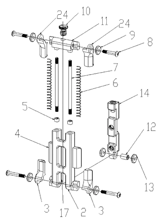
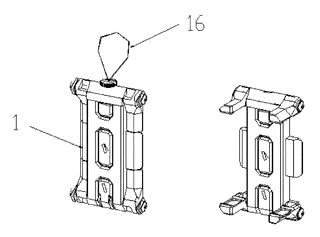
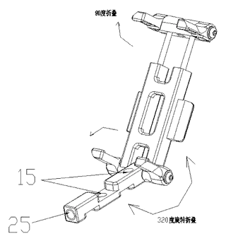
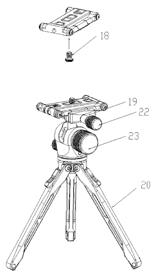
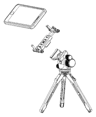
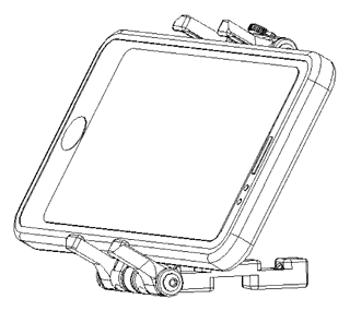
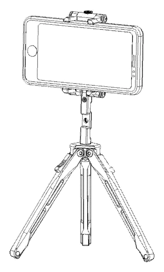
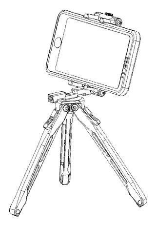
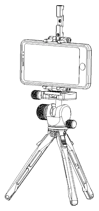
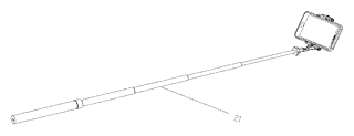
Drawings reproduced from the public patent document for reference.