At a glance
| Patent number | CN207534578U (application CN201721735620) |
| Type | China utility model (实用新型) - protects product shape and structure |
| Original title | A kind of angle grinder with cooling and dedusting function (一种具有降温和除尘功能的角磨机) |
| Patent owner | Zhejiang Fujian Power Tools Co Ltd |
| Inventors | Zhu Mingliang |
| Filing date | 2017-12-13 |
| Grant date | 2018-06-26 |
| Status (China) | In force in China until at most 2027-12-13 (if annual fees are paid) |
| Patent family | Chinese filings only - no US, European, Japanese, PCT or other filings listed |
| Cited by | 6 later documents |
| Source | Google Patents (search for CN207534578U) |
What the claims cover, in plain language
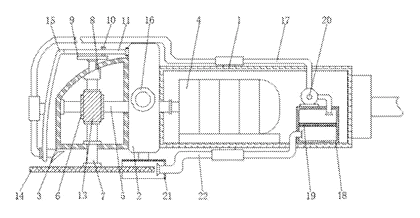
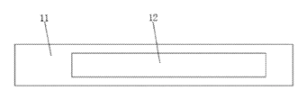
Claim 1 defines the core mechanical layout: a casing body (1) connected via a connecting plate (2) to a transmission casing (3). Inside the casing body, a power motor (4) drives a drive link (5) through a coupling. The drive link extends through the connecting plate into the transmission casing, where it carries a transmission worm gear (6). A swingle or spindle (7) is supported by bearings at the bottom of the transmission casing. A retarder or speed reducer (8) is fixed at the top of the transmission casing, connecting its bottom to the top of the swingle. The output shaft of the retarder extends upward through the transmission casing and attaches to a turntable (9). A sliding bar (10) is fixed on top of the turntable. An oscillating deck (11) is rotatably connected to the side of the connecting plate, featuring a sliding groove (12) that receives the sliding bar, converting the turntable’s rotation into a back-and-forth swinging motion of the deck.
Claim 2 specifies the drive train: a worm screw sleeve (13) on the swingle meshes with the transmission worm gear. The bottom of the swingle extends below the transmission casing to mount the grinding disc (14).
Claim 3 covers the air delivery path: an arc mounting bracket (15) is fixed to the side of the oscillating deck away from the connecting plate. A soft air-guide pipe (17) is attached to this bracket. On the opposite side of the casing body’s inner wall bottom, a Rose Box or filter box (18) is installed, containing a filter screen (19).
Claim 4 details the fan arrangement: an exhaust fan (20) is fixed on top of the Rose Box. Its air outlet connects to one end of the soft air-guide pipe, while its air inlet connects via a blast pipe to the top side of the Rose Box.
Claim 5 describes the dust intake route: a protective cover (21) is fixed to the bottom of the connecting plate via a connecting rod. An exhaust column (22) is mounted on the side of the protective cover, passing sequentially through the casing body and into the interior of the Rose Box.
Claim 6 lists the user interfaces: a control switch (23) on the front side of the casing body, a hinged chamber door (24) on the opposite front side for accessing the filter box, and a handle (16) mounted on the front of the connecting plate.
This is a simplified reading for orientation only. The legal scope is defined by the exact claim wording in the official Chinese document.
What this means for US production
This patent was filed only in China. It is currently in force in China until at most 2027-12-13 (if annual fees are paid), meaning manufacturing or selling this specific design within China requires the patent owner’s permission. It has no US or other foreign counterpart.
Two points to settle early:
- Freedom to operate (FTO). While this specific Chinese utility model does not restrict production outside China, the broader category of power tools with integrated dust extraction is heavily patented globally. Major power tool manufacturers hold numerous US and international patents covering shrouds, vacuum ports, cyclonic separators and active cooling mechanisms for grinders. A thorough FTO review focusing on the dust routing path, filter placement and oscillating air delivery mechanism is essential before committing to tooling for the US market.
- Motor and electrical architecture. The patent describes the mechanical layout but does not specify whether the motor is brushed or brushless, nor the voltage or amperage ratings. These parameters must be defined during engineering to match target market requirements and ensure adequate power for both the grinding spindle and the exhaust fan.
Customization and manufacturing
What can be customized
| Area | Options |
|---|---|
| Disc diameter | Tooling adapted for common sizes such as about 4.5 in. (115 mm) or 5 in. (125 mm) |
| Motor type | Brushed or brushless DC/AC motor configurations depending on performance targets |
| Filter media | Standard mesh screen, pleated paper cartridge, or HEPA-grade filter element |
| Housing material | Glass-filled nylon, polycarbonate blends, or aluminum die-cast for heavy-duty variants |
| Air duct | Silicone or thermoplastic elastomer for the soft guide pipe; varying lengths and nozzle shapes |
| Power input | Corded (120V/240V) or cordless (battery pack interface to be confirmed in design) |
| Handle ergonomics | Overmolded grip textures, adjustable auxiliary handle positions |
Things to plan for (US market)
- UL 62841-2-3 / CSA C22.2 No. 62841-2-3 - the primary safety standard for hand-held motor-operated grinders sold in North America, covering electrical insulation, mechanical strength, thermal limits and guarding.
- OSHA Respirable Crystalline Silica Standard (29 CFR 1926.1153) - if marketed for construction or masonry use, the tool’s dust capture efficiency will be evaluated against Table 1 requirements for engineering controls.
- FCC Part 15 - if the design incorporates a brushless motor with electronic speed control or any wireless features, electromagnetic interference testing is required.
- California Proposition 65 - materials used in the housing, grips, filter screens and wiring must be screened for listed chemicals, and appropriate warnings applied if necessary.
How a project runs
- Inquiry - define target disc size, motor power, filtration goals and estimated volumes.
- Design - engineer the casing mold, transmission gear ratios, fan impeller, oscillating linkage and filter box sealing.
- Prototype - produce functional samples via CNC machining or soft tooling to verify dust capture flow rates, cooling sweep coverage and vibration levels.
- Pilot run - manufacture a small batch using production molds for third-party safety certification testing (e.g., UL listing) and durability validation.
- Production - scale up injection molding, die casting, gear hobbing, motor winding and final assembly with inline quality checks.
Quantities & timeline
Manufacturing this tool requires significant upfront investment in injection molds for the complex casing body and transmission housing, precision tooling for the worm gear set, stamping dies for the oscillating linkage, and assembly fixtures for the motor and fan integration. Safety certification testing adds lead time before volume shipments can begin. Send us your specifications regarding disc size, power source, filtration requirements, estimated quantity and target price and we will reply with options.
Patent drawings
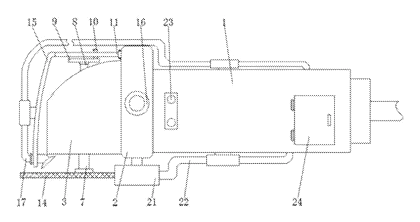
Drawings reproduced from the public patent document for reference.