
Patent CN207616512U
Updated November 5, 2026Hammer with Integrated LED Lighting and Storage Compartment
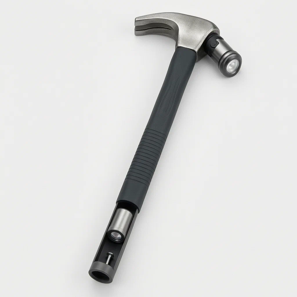
Working in dim basements, attics, or night-time repair sites often means juggling a flashlight and a hammer, leaving one hand occupied. This patent presents a solution by integrating a screw-on LED module directly into the hammer's handle. The lamp stand attaches via threads at the butt end, allowing it to point outward for lighting or inward for protection. Simultaneously, the handle’s interior is hollowed out to create a storage chamber with a sliding tray, keeping essential fasteners within reach. It turns a standard striking tool into a self-contained lighting and storage hub.
- China utility model - lapsed
- No filings outside China
- Hand tools & workshop equipment
- Integrated LED lighting and storage features
Splat! What let you down?
💡
Screw-on LED Module
The handle end accepts a threaded lamp stand with an integrated LED, battery, and switch.
🔄
Dual Orientation
The light can face outward for illumination or inward to protect the lens during storage.
📦
Internal Storage Tray
A hollow handle contains a removable tray and cap for storing nails, screws, or bits.
🔩
Modular Design
The lighting unit is fully detachable, allowing the hammer to be used without it.
Bring this product to market
- ✓ Patent review Patent family and legal status reviewed in the relevant jurisdictions.
- 2 Product brief · now How it works, uses and options written up
- 3 Prototype First samples for buyers to review
- 4 Pilot run Small first batch for launch customers
- 5 Volume production Repeat orders at scale
Buyer interest
– of 100 buyers needed to start prototyping
One click, no sign-up. Each vote is one real visitor, and products with the most interest go to prototyping first.
Build team: no members yet. Need a partner, co-funding or skills to build this? Join and we introduce the team once it forms.
Patent Rights & Team Participation
Before joining a development team, participants should ensure they have the necessary rights or authorization to participate in the project.
Participation is generally appropriate where:
- You own the relevant patent rights or have obtained permission or a license from the rights holder.
- The relevant patent rights have expired or have been legally invalidated in the jurisdictions where the planned activities will take place.
- The planned development, manufacturing, and commercialization activities have been independently assessed and do not infringe applicable patent rights in the relevant jurisdictions.
Important: Being located outside a country where a patent is protected does not automatically exempt you from patent infringement risks. Patent rights may apply based on where development, manufacturing, use, sale, or import activities take place.
IP2M does not grant any patent license or authorization through team participation. Joining a project does not provide permission to use, manufacture, or commercialize patented technology.
The problem
Traditional hammers are simple striking tools. In low-light environments like basements, crawl spaces, or during evening repairs, users must hold a separate flashlight, which occupies a hand and reduces control over the hammer. Additionally, small fasteners like nails, screws, or drill bits are often kept in pockets or nearby containers, leading to lost items and inefficient workflow. There is a need for a compact tool that provides hands-free illumination and immediate access to small hardware without increasing bulk significantly.
The solution
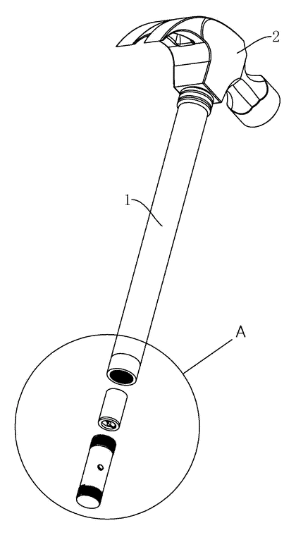
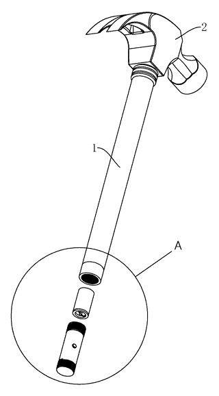
- Handle Structure: The hammer consists of a head (tup) fixed to one end of a cylindrical handle. The opposite end of the handle features a mounting base with a central threaded hole.
- Lighting Device: A separate lamp stand contains an LED headlamp, a power supply (battery), and a control switch. The lamp stand has two sets of external threads: one near the light source and one at the far end.
- Attachment Mechanism: The lamp stand screws into the handle’s mounting base. Depending on which thread engages the base, the light can face outward (to illuminate the work area) or inward (into the handle cavity).
- Storage Chamber: The interior of the handle is hollowed out to form a storage chamber. This chamber runs along the length of the handle.
- Removable Tray: Inside the storage chamber sits a parcel tray shaped to fit the cavity. The tray has an opening covered by an end cap with a connecting pole and gripper ring, allowing it to be pulled out easily.
Who it is for
- Home Improvement DIYers who frequently work in poorly lit areas like garages or under sinks and want to keep their hands free.
- Professional Electricians and Plumbers who need quick access to small connectors and reliable lighting while working in tight, dark spaces.
- Automotive Mechanics repairing vehicles in pits or dimly lit shops, benefiting from the integrated light and storage for bolts and clips.
- Maintenance Staff in facilities management who carry a multi-purpose tool for minor repairs involving both striking and fastening.
How it works
The main parts
| No. | Part | What it does |
|---|---|---|
| 1 | Handle | Cylindrical grip; houses the storage chamber and mounting base. |
| 2 | Tup (Head) | The striking surface of the hammer. |
| 3 | Lighting Device | Modular unit comprising the lamp stand, LED, and electronics. |
| 4 | Lamp Stand | Cylindrical housing for the light; features external threads (9, 10). |
| 5 | Headlamp | LED light source at one end of the stand. |
| 6 | Vessel | Internal compartment in the lamp stand holding the battery. |
| 7 | Power Supply | Battery (e.g., dry cell) powering the LED. |
| 8 | Control Switch | Button on the lateral wall of the lamp stand to turn the light on/off. |
| 9, 10 | Threads | First and second screw threads on the lamp stand for attachment. |
| 11 | Mounting Base | End of the handle with a threaded hole (12) to receive the lamp stand. |
| 12 | Threaded Hole | Connects to the lamp stand threads. |
| 13 | Groove | Shaped recess at the bottom of the threaded hole to house the LED head when inverted. |
| 14 | Storage Chamber | Hollow space inside the handle for the tray. |
| 15 | Parcel Tray | Removable container inside the storage chamber. |
| 16 | Opening | Access point for the tray. |
| 17 | End Cap | Covers the tray opening. |
| 18 | Connecting Pole | Interference-fit stem attaching the cap to the tray. |
| 19 | Gripper Rings | Articulated rings on the cap for pulling the tray out. |
Operating Steps
- Assembly: Screw the lamp stand into the handle’s mounting base. Use the first thread (9) to have the light face outward for illumination, or the second thread (10) to have the light face inward for protection.
- Activation: Press the control switch (8) on the side of the lamp stand to complete the circuit between the battery (7) and the LED (5).
- Storage Access: Pull the gripper rings (19) on the end cap (17) to slide the parcel tray (15) out of the handle’s storage chamber (14).
- Detachment: Unscrew the entire lighting device if a standard hammer is preferred, leaving the handle intact.
Applications
Basement and Attic Repairs
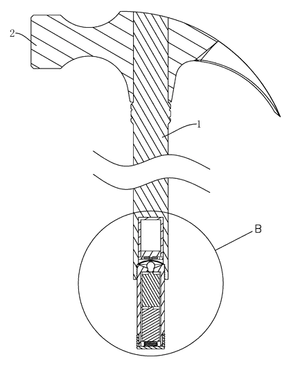
Users working in unlit corners of homes can attach the light to the hammer handle, illuminating joists or wiring without needing a separate torch, while keeping nails in the handle tray.
Automotive Under-Car Work
Mechanics lying under vehicles can use the hammer to tap components loose while the attached LED lights up the specific bolt or bracket they are targeting, with spare fasteners stored within arm’s reach.
Electrical Panel Maintenance
Electricians opening panels in dim rooms can screw the light onto the hammer to see terminal blocks clearly, using the internal tray to store wire nuts or small screws removed during service.
Night-Time Outdoor Maintenance
Facility staff performing emergency repairs after dark can rely on the integrated light to see hazards and work areas, reducing the risk of dropping a flashlight and losing sight of the task.
Where it is less suitable
- Heavy Industrial Demolition: The plastic or lightweight metal components of the lighting module may not withstand extreme vibration or impact forces compared to solid steel handles.
- Wet Environments: Unless specifically sealed, the open threads and button switch may be susceptible to water ingress or corrosion in rainy conditions.
- Precision Craftsmanship: The added bulk of the battery and lamp stand changes the hammer’s center of gravity, potentially affecting balance for delicate woodworking tasks.
Patent & Production
At a glance
| Patent number | CN207616512U (application CN201721558271) |
| Type | China utility model (实用新型) - protects product shape and structure |
| Original title | Novel Hammer (新型锤子) |
| Patent owner | Tianjin Urban Construction Road And Bridge Engineering Co Ltd |
| Inventors | Liu Linhua |
| Filing date | 2017-11-20 |
| Grant date | 2018-07-17 |
| Status (China) | Lapsed - terminated for non-payment of annual fees (recorded 2021-10-29) |
| Patent family | Public record shows Chinese filings only - no US, European, Japanese, PCT or other filings listed |
| Cited by | 1 later document (EP3825082A1 by Vision Devices GmbH) |
| Source | Google Patents (search for CN207616512U) |
What the claims cover, in plain language
Claim 1 defines a hammer comprising a handle and a tup (head). A lighting device is included, consisting of a lamp stand with a headlamp. The lamp stand has a vessel for a power supply and a control switch on its lateral wall. The peripheral surface of the lamp stand features a first screw thread near the headlamp and a second screw thread away from it. The handle’s end face has a mounting base with a threaded hole designed to connect with either the first or second screw thread.
Claims 2-9 add details such as a groove at the bottom of the threaded hole to house the headlamp shell, a storage chamber within the handle aligned with the threaded hole, a parcel tray fitting into this chamber, and an end cap with a connecting pole and gripper rings for retrieving the tray.
This is a simplified reading for orientation only. The legal scope is defined by the exact claim wording in the official Chinese document.
What this means for US production
This patent was filed in China and has lapsed, so it no longer restricts anyone in China. The public record shows no US or other foreign counterpart.
Two points to settle early:
- Other patents may exist. Hand tools with integrated lights are a competitive field. While this specific utility model is expired, later foreign patents citing this document (such as EP3825082A1 held by Vision Devices GmbH) indicate ongoing innovation in illuminated tools. A freedom-to-operate (FTO) review is recommended to ensure no active US patents cover similar threading mechanisms or internal storage configurations in hammers.
- Electrical Safety. Since the design includes a battery and electrical circuit, US market entry requires adherence to specific safety standards for consumer products containing batteries.
Customization and manufacturing
What can be customized
| Area | Options |
|---|---|
| Light Source | LED color temperature (warm/cool white), brightness level, battery type (AAA, coin cell, rechargeable USB). |
| Handle Material | Fiberglass, steel, or aluminum core with rubber overmolding for grip. |
| Storage Capacity | Diameter and depth of the internal chamber; size of the removable tray. |
| Thread Type | Metric or imperial thread pitch for the lamp stand attachment. |
| Finish | Powder coating, chrome plating, or textured rubber grips. |
Things to plan for (US market)
- CPSC Regulations: General safety requirements for household tools.
- Battery Compliance: UN 38.3 for shipping lithium batteries (if applicable); FDA 21 CFR if marketed for food-related industries (unlikely but check labeling).
- FCC Part 15: If the lighting module uses wireless charging or any radio frequency components, FCC certification is needed. Standard LED circuits typically do not require FCC ID unless they emit significant interference.
- OSHA Standards: For industrial use, ensuring the tool does not present pinch hazards or electrical shock risks.
How a project runs
- Inquiry - Define target load class, light specs, and storage volume.
- Design - Finalize handle geometry, thread interface, and tray mechanism.
- Prototype - 3D print handle and machining test parts; assemble functional sample.
- Pilot Run - Test durability of threads and drop tests for the lighting module.
- Production - Die-cast or forge heads, injection mold lamp stands, assemble.
Quantities & timeline
Tooling costs are driven by the complexity of the handle’s internal cavity and the precision required for the screw threads. Injection molds for the lamp stand and tray are necessary. Assembly involves inserting electronics and testing each unit. Send us your specifications for light output, handle material, and estimated quantity and we will reply with options.
Patent drawings
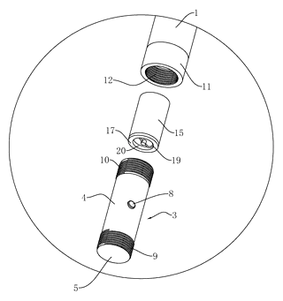
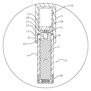
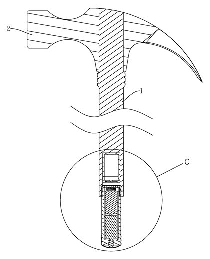
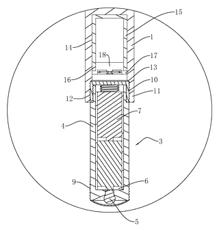
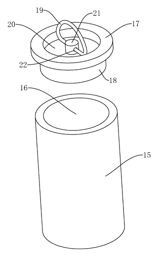
Drawings reproduced from the public patent document for reference.
Production notes
Tooling and process
The handle likely requires die-cast aluminum or forged steel, followed by machining to create the internal storage chamber and precise threads. The lamp stand is typically glass-filled nylon injection molding to resist impact. Heat treatment may be applied to the hammer head for hardness.
Cost drivers
Material selection (especially if using high-grade alloys for the handle) and the number of stamping dies or injection molds typically drive initial costs. Cutting edge machining for the threads adds time. Surface finish quality also impacts price.
Prototyping path
Prototyping typically starts with a 3D-printed handle to verify ergonomics and thread fit. Use machined or off-the-shelf blades for the head. Create heat-treatment trial coupons to validate strength before committing to full tooling.
What we would change before tooling
We would refine the thread engagement tolerance to prevent stripping under torque. The snap-fit or press-fit pins for the tray mechanism should be tested for retention strength. Ensuring proper strain relief for any internal wiring in the lamp stand is critical.
Common failure points
Edge hardness below spec can lead to chipping. Pivot pin wear (if articulated parts are used) or spring fatigue in the gripper rings could cause loss of function. Thread engagement issues may result in the light detaching during use. Handle creep under heavy impact loads is a structural risk to monitor.
Frequently asked questions
How does the light attach to the hammer?
The lamp stand has two sets of threads. You screw it into the mounting base at the end of the handle. One thread orientation makes the light face outward for working; the other makes it face inward to protect the lens when stored.
Can I remove the light completely?
Yes. The lighting device is modular. Unscrewing it entirely leaves you with a standard hammer. The handle remains usable without the light attachment.
What fits in the storage chamber?
The internal tray is designed for small fasteners like nails, screws, drill bits, or anchors. The exact capacity depends on the final design dimensions, which are confirmed on prototypes.
Is the hammer balanced with the light attached?
Adding the light shifts the center of gravity slightly toward the handle end. Manufacturers typically adjust the head weight or handle thickness to maintain a comfortable swing feel.
Does it use rechargeable batteries?
The patent mentions a power supply in a vessel, preferably a dry cell. Custom versions can be designed with rechargeable lithium-ion cells and USB charging ports, depending on the model.
Is it safe to use in wet conditions?
Standard models may not be waterproof. If you need to work in rain or damp areas, look for IP-rated seals on the switch and threads, which can be specified in custom orders.
Can this design be made and sold in the US?
The patent was filed in China and has lapsed, and the public record shows no US counterpart, so it does not restrict the design in the US. However, illuminated tools are a crowded field, so we recommend a freedom-to-operate check to ensure no other active US patents cover specific features like the dual-thread orientation or internal tray mechanism.
Are you affiliated with the patent owner?
No. IP2M is an independent design and manufacturing service working from the public patent document.
Request a quote
Click Request a Quote below to see our email address - copy it, or open your email app with a ready-made message. Please mention patent CN207616512U in the subject.
Helpful details to include:
- Your company and channel (hardware brand, automotive supplier, DIY retailer)
- Target user (professional vs. home use)
- Light specs (brightness, battery type, runtime)
- Storage needs (types of fasteners to hold)
- Estimated quantity and target price
- Timeline - when you would like samples and the first shipment
You can also reach us at (332) 203-9997.
Page editor: Emily Zhang, Product Editor · IP2M
Last updated November 5, 2026. If something on this page looks wrong, email [email protected] and we will check it against the patent.
Interested in building this?
Tell us your target market, quantity and timeline. We reply with options for prototyping, small-batch runs or volume production.
Send your inquiry to
Please put CN207616512U in the subject line and tell us your company, country, estimated quantity and timeline.
Prefer to talk? Call (332) 203-9997.
More product-ready patents
All Tools & Workshop patents →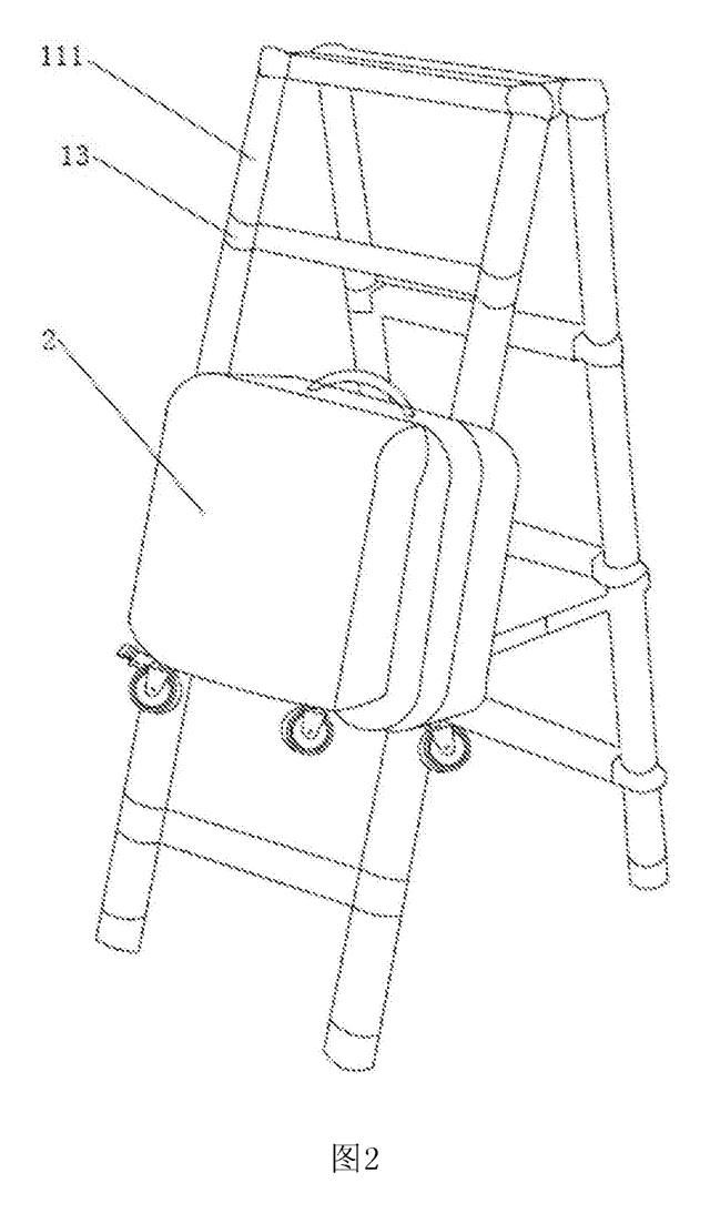
Tools & Workshop
Rolling Tool Box with Telescoping Step Ladder
Telescoping A-frame ladder with an attached rolling tool box that slides to your working height.
Patent CN206290197U
Tools & Workshop
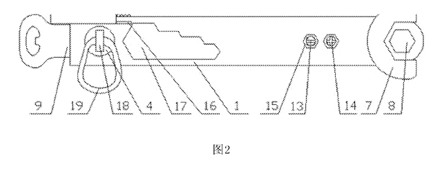
Folding 3-Handle Wrench Multi-Tool
Folding three-handle wrench multi-tool with magnetic screwdriver bits, saw, file and bottle opener.
Patent CN205290875U
Tools & Workshop
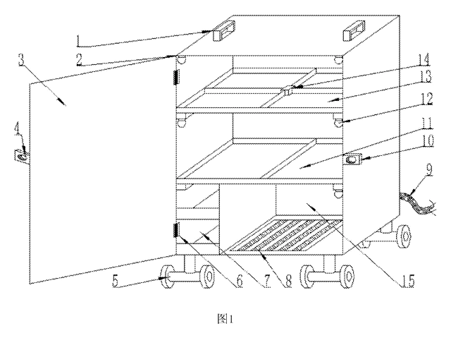
Rolling Auto-Repair Tool Cabinet with Built-In Lights
Lockable rolling tool cabinet for car repair with interior lights, a lubricant tray, parts drawers and a tool bay.
Patent CN205989314U
Tools & Workshop
Wide-Opening Folding Bolt Cutter
Bolt cutter with linked, gear-meshing handles that open up to 190° and fold in half for storage.
Patent CN207206226U
Tools & Workshop
Nail-Holding Hammer with Fold-Out Drivers
Hammer with a nail-holding T-slot in the head and fold-out drivers stored in the handle.
Patent CN205254927U
Tools & Workshop
Modular Wrench with Screw-On Heads
Wrench handle with a three-way threaded hub for screw-on adjustable and hex heads, plus a pipe sleeve.
Patent CN206216564U
Browse by category
- Apparel & Accessories (39)
- Baby & Kids (26)
- Bags & Luggage (15)
- Bath & Personal Care (26)
- Car Accessories (21)
- Furniture, Bedding & Storage (21)
- Garden & Outdoor (29)
- Health & Wellness (12)
- Home, Kitchen & Cleaning (43)
- Lighting (20)
- Packaging & Containers (10)
- Pet Products (10)
- Phone & Camera Accessories (8)
- Retail Display (22)
- School, Office & Art (30)
- Sports & Recreation (39)
- Tools & Workshop (48)
- Toys & Games (20)
This page is based on the public patent document CN207616512U, assigned to Tianjin Urban Construction Road And Bridge Engineering Co Ltd. IP2M is an independent manufacturing service and is not affiliated with, endorsed by or licensed by the patent owner. Images marked as concept renderings are illustrations, not photos of an existing product. Patent status information is provided for reference only and is not legal advice; confirm freedom to operate for your market before production. Full disclaimer.