
Patent CN208084294U
Updated October 28, 2026Double-Folding Workbench with Three-Part Tabletop and Telescopic Legs
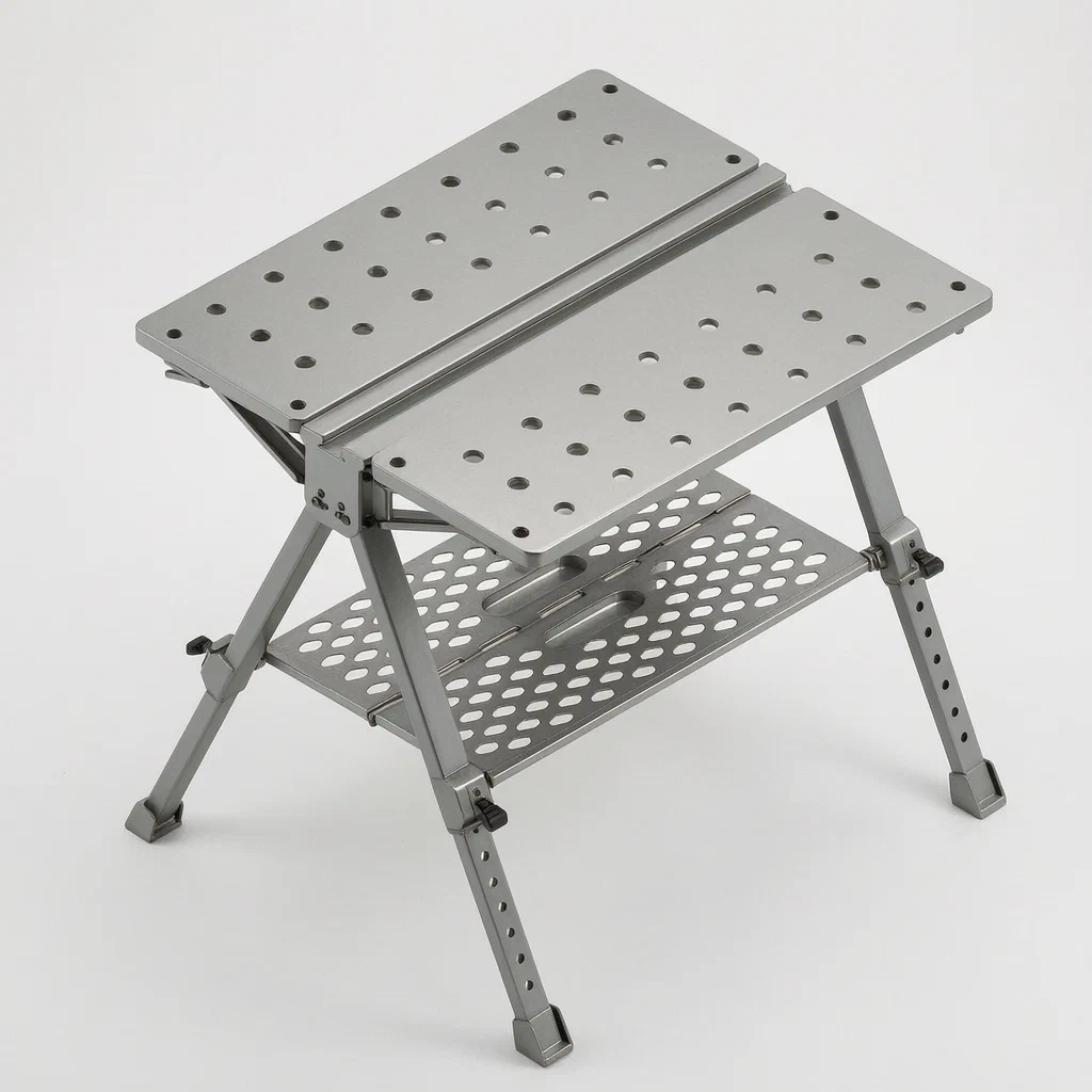
Standard portable workbenches often serve a single purpose and take up floor space even when not in use. This double-folding design addresses that by combining a work surface with a saw stool function in one frame. The tabletop splits into three sections: a central cross-member and two side deck plates connected by triangular folding racks. When the job is done, the deck plates fold down and the telescopic legs retract, reducing the footprint for transport or storage. Mounting holes arranged in a matrix on both deck plates accept standard workshop fixtures, while a recessed mounting groove running along the top of the cross-member holds clamps or guides. The legs adjust via inner and outer rods locked by a pin-and-spring control, allowing the user to set the working height.
- China utility model - in force
- No filings outside China
- Workshop & job-site furniture
- Steel tubing, stamped plates, torsion spring hinges
Splat! What let you down?
🪵
Dual-purpose surface
Functions as both a general workbench and a saw stool, overcoming the single-use limitation of typical portable benches.
🔩
Fixture-ready deck plates
Left and right plates feature multiple vertically penetrating mounting holes arranged in a matrix for workshop clamps and stops.
📐
Recessed mounting groove
A groove runs along the cross-member's upper face, rectangular at the top and isosceles-trapezoidal below, for holding guides.
🦵
Telescopic legs with pin lock
Inner and outer foot rods align via adjustment holes and a spring-loaded pin control to set the working height.
Bring this product to market
- ✓ Patent vetted China-only family and legal status checked
- 2 Product brief · now How it works, uses and options written up
- 3 Prototype First samples for buyers to review
- 4 Pilot run Small first batch for launch customers
- 5 Volume production Repeat orders at scale
Buyer interest
– of 100 buyers needed to start prototyping
One click, no sign-up. Each vote is one real visitor, and products with the most interest go to prototyping first.
Build team: no members yet. Need a partner, co-funding or skills to build this? Join and we introduce the team once it forms.
The problem
Portable workbenches used on job sites or in small workshops typically offer a single flat surface. When a worker needs to support long stock for cutting, they must bring a separate saw stool or improvise with sawhorses. Switching between tasks means moving equipment around, which takes time and floor space. Furthermore, many folding tables use simple hinges that lack rigidity when extended, causing the surface to wobble under lateral pressure. Storage is another issue: even when folded, basic designs leave the legs protruding or the tabletop too thick to slide into a vehicle easily. A bench that can change its profile, hold fixtures securely, and pack down tightly addresses these daily friction points for tradespeople and DIY users alike.
The solution
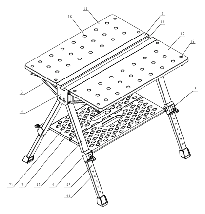
The patent describes a double-folding workbench built around a central cross-member (1) with two hinged side plates.
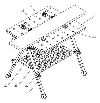
- A left deck plate (11) and a right deck plate (12) attach to the cross-member (1) via folding racks (6). Both plates contain multiple mounting holes (18) that penetrate vertically, arranged in a matrix pattern to accept standard workshop fixtures.
- The upper face of the cross-member (1) has a recessed mounting groove (10) extending from one end to the other. The groove’s cross-section is rectangular in the upper portion and isosceles trapezoidal in the lower portion, meaning the first half’s width is less than the lower half’s width.
- Tripod support elements (4), which are U-shaped, are fixed to both ends of the cross-member (1). Each element consists of an end support plate and two side support plates.
- Two foot levers hinge onto each tripod support element (4). Every foot lever uses an inner foot rod (41) socketed inside an outer foot rod (42). The inner rod has several adjustment holes (43) that align with a location hole on the outer rod.
- A telescoping control (5) sits at the location hole, using a pin member (51) pushed by a spring (52) to lock the height.
- The folding rack (6) forms a triangular linkage using a first rod piece (61), a second rod piece (62) with a horizontal sliding slot (65), an inclined third rod piece (63), and a fourth rod piece (64) held by an elastic torsional spring (69) to engage a limiting slot (60) for stability when open.
Who it is for
- Power tool brands looking to bundle a dedicated saw stool and workbench with their miter saws or circular saws for retail kits.
- Contractors and carpenters who move between job sites daily and need a rigid, adjustable-height surface that fits inside a van when folded.
- Home improvement retailers selling to DIY customers who lack space for a permanent workbench but require a sturdy platform for weekend projects.
- Wholesalers of workshop equipment seeking a compact, dual-function product that reduces SKU counts by replacing separate sawhorses and assembly tables.
How it works
The main parts
| No. | Part | What it does |
|---|---|---|
| 1 | Cross-member | Central horizontal beam forming the core of the tabletop. |
| 10 | Mounting groove | Recessed channel on the cross-member for holding clamps or guides. |
| 11, 12 | Left / Right deck plates | Hinged side surfaces with matrix mounting holes for fixtures. |
| 18 | Mounting holes | Vertical holes in the deck plates for attaching workshop accessories. |
| 4 | Tripod support element | U-shaped bracket at each end connecting the cross-member to the legs. |
| 41, 42 | Inner / Outer foot rods | Telescoping tubes that form the adjustable legs. |
| 43 | Adjustment holes | Spaced holes on the inner rod for setting leg height. |
| 5 | Telescoping control | Pin-and-spring mechanism locking the inner and outer rods together. |
| 6 | Folding rack | Triangular linkage connecting the deck plates to the cross-member. |
| 61–64 | Rod pieces | First through fourth bars making up the folding rack geometry. |
| 65 | Sliding slot | Horizontal slot in the second rod piece guiding the third rod piece. |
| 69 | Elastic torsional spring | Spring biasing the fourth rod piece to lock the rack in position. |
Operating steps
- Unfold the legs - Pull the outer foot rods (42) down. Align the desired adjustment hole (43) on the inner foot rod (41) with the location hole on the outer rod. Press the telescoping switch part (54) to release the pin member (51), set the height, and let the spring (52) push the pin back in to lock.
- Extend the tabletop - Lift the left deck plate (11) and right deck plate (12) outward. The folding rack (6) opens as the third rod piece (63) slides along the sliding slot (65) of the second rod piece (62). The elastic torsional spring (69) forces the fourth rod piece (64) so its limiting slot (60) engages the third shaft (67), locking the plates flat.
- Mount fixtures - Insert clamps, stops, or guides into the mounting holes (18) on the deck plates or slide them into the mounting groove (10) on the cross-member (1).
- Fold for transport - Disengage the limiting slot (60) from the third shaft (67) to collapse the folding racks (6), dropping the deck plates downward. Retract the legs using the telescoping control (5).
Applications
Carpentry and trim work
Carpenters installing baseboards or crown molding need a stable surface to measure and cut. The mounting holes allow them to fix a stop block, while the recessed groove holds a straight edge. The telescopic legs let them match the bench height to their existing saw stand.
Job-site material prep
On construction sites, workers frequently cut hardware or prepare fasteners. Setting this workbench up takes seconds because the folding racks lock mechanically without tools. When the task shifts to another room, the folded unit is carried like a briefcase.
DIY garage projects
Home users often lack the floor space for a permanent woodworking table. This design folds down so it can be hung on a wall hook or slid behind shelving. The matrix of mounting holes accepts common hobbyist clamps for gluing or painting small assemblies.
Miter saw support
When cutting long lumber with a miter saw, the outfeed side needs support at the exact same height. The adjustable inner and outer foot rods allow precise leveling. The deck plates provide a broad, flat landing area for the offcut.
Where it is less suitable
- Heavy industrial machining - the tubular legs and hinged plates are designed for hand tools and portable power tools, not the vibration or weight of stationary milling machines.
- Permanent assembly lines - factory stations generally require fixed, bolted-down benches rather than folding mechanisms intended for portability.
Frequently asked questions
How do the deck plates stay flat when opened?
Each deck plate connects to the central cross-member via a triangular folding rack. When the plate is lifted, a third rod piece slides along a horizontal slot in a second rod piece. An elastic torsional spring pushes a fourth rod piece so that its limiting slot snaps over a shaft on the third rod piece, locking the assembly rigidly in the open position.
What fixtures fit the mounting holes?
The patent specifies that the holes penetrate vertically through the left and right deck plates and are arranged in a matrix. The exact diameter and spacing are set in design to match standard workshop clamps, bench dogs, or accessory stops chosen by the manufacturer.
How does the height adjustment work?
Each leg consists of an inner foot rod sliding inside an outer foot rod. The inner rod has a series of adjustment holes. A telescoping control uses a spring-loaded pin member that passes through a location hole in the outer rod. Pulling the switch part retracts the pin, allowing the user to slide the leg to the desired height before releasing the switch so the spring pushes the pin into the next aligned hole.
Can it really be used as a saw stool?
Yes. The patent describes the design as having both a workbench function and a saw stool function. By adjusting the telescopic legs to match the height of a miter saw or table saw, the deck plates act as an outfeed support for long boards.
What is the recessed groove on the center beam for?
The mounting groove runs along the upper face of the cross-member from end to end. Its cross-section is rectangular at the top and isosceles trapezoidal at the bottom. This shape allows specialized clamps or guide rails to be seated securely in the center of the table.
How small is it when folded?
The patent states the equipment is integrally foldable, readily transported, and has a small parking space. Exact folded dimensions depend on the length of the cross-member and the retracted leg length, which are confirmed on prototypes during development.
Can this design be made and sold in the US?
The patent was filed only in China and is currently in force there (until at most 2028-04-01, if annual fees are paid). It has no US counterpart, so it does not restrict manufacturing or selling the design in the United States. However, other companies hold later US and international patents citing this document in the folding workbench field, so a freedom-to-operate review is recommended before volume production.
Are you affiliated with the patent owner?
No. IP2M is an independent design and manufacturing service working from the public patent document.
Request a quote
Click Request a Quote below to see our email address - copy it, or open your email app with a ready-made message. Please mention patent CN208084294U in the subject.
Helpful details to include:
- Your company and sales channel (power tool brand, home improvement retailer, wholesale distributor, Amazon seller)
- Target tabletop dimensions and preferred deck plate material
- Fixture compatibility required for the mounting holes
- Height range needed for the telescopic legs
- Estimated quantity and destination market
- Timeline - when you would like prototypes and the first shipment
You can also reach us at (332) 203-9997.
Explore this product
Interested in building this?
Tell us your target market, quantity and timeline. We reply with options for prototyping, small-batch runs or volume production.
Send your inquiry to
Please put CN208084294U in the subject line and tell us your company, country, estimated quantity and timeline.
Prefer to talk? Call (332) 203-9997.
More product-ready patents
All Tools & Workshop patents →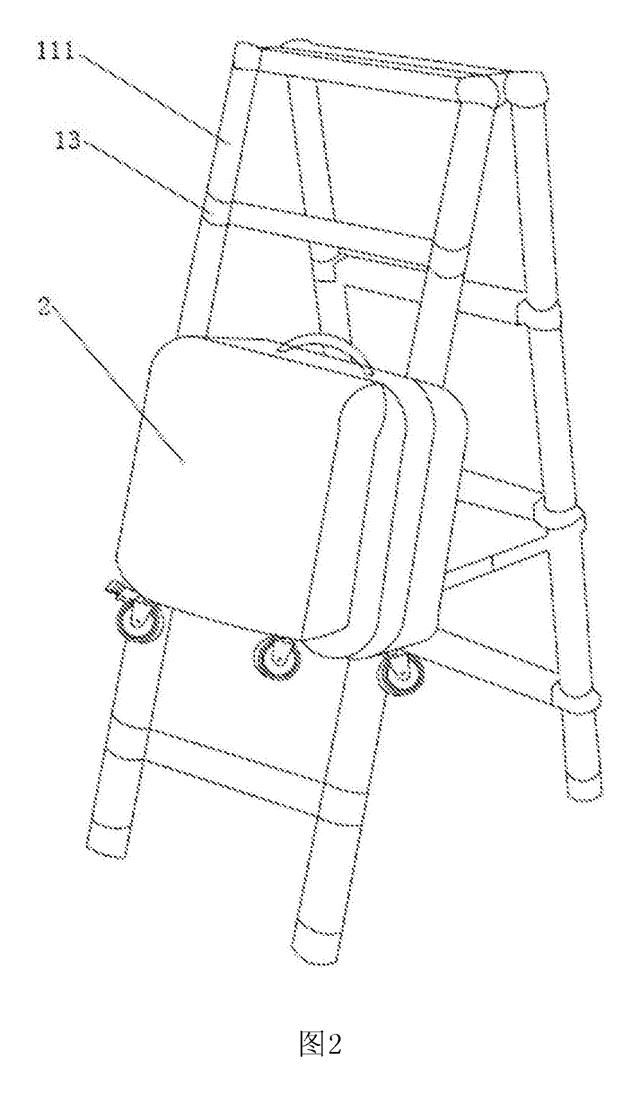
Tools & Workshop
Rolling Tool Box with Telescoping Step Ladder
Telescoping A-frame ladder with an attached rolling tool box that slides to your working height.
Patent CN206290197U
Tools & Workshop
Folding 3-Handle Wrench Multi-Tool
Folding three-handle wrench multi-tool with magnetic screwdriver bits, saw, file and bottle opener.
Patent CN205290875U
Tools & Workshop
Rolling Auto-Repair Tool Cabinet with Built-In Lights
Lockable rolling tool cabinet for car repair with interior lights, a lubricant tray, parts drawers and a tool bay.
Patent CN205989314U
Tools & Workshop
Wide-Opening Folding Bolt Cutter
Bolt cutter with linked, gear-meshing handles that open up to 190° and fold in half for storage.
Patent CN207206226U
Tools & Workshop
Nail-Holding Hammer with Fold-Out Drivers
Hammer with a nail-holding T-slot in the head and fold-out drivers stored in the handle.
Patent CN205254927U
Tools & Workshop
Modular Wrench with Screw-On Heads
Wrench handle with a three-way threaded hub for screw-on adjustable and hex heads, plus a pipe sleeve.
Patent CN206216564U
Browse by category
- Apparel & Accessories (22)
- Baby & Kids (16)
- Bags & Luggage (9)
- Bath & Personal Care (16)
- Car Accessories (10)
- Furniture, Bedding & Storage (12)
- Garden & Outdoor (18)
- Health & Wellness (8)
- Home, Kitchen & Cleaning (24)
- Lighting (12)
- Packaging & Containers (6)
- Pet Products (6)
- Phone & Camera Accessories (4)
- Retail Display (13)
- School, Office & Art (19)
- Sports & Recreation (25)
- Tools & Workshop (27)
- Toys & Games (12)
This page is based on the public patent document CN208084294U, assigned to Jinhua Yahu Tools Co Ltd. IP2M is an independent manufacturing service and is not affiliated with, endorsed by or licensed by the patent owner. Images marked as concept renderings are illustrations, not photos of an existing product. Patent status information is provided for reference only and is not legal advice; confirm freedom to operate for your market before production. Full disclaimer.