
Patent CN208876424U
Updated November 1, 2026Ratchet-Driven Spin Mop Head with Fixed Twist Rod
Traditional spin mops often require vigorous wrist twisting or large vertical movements to engage the spinning mechanism, leading to fatigue. This patent describes a mop head with a built-in ratchet system. When the inner rod moves upward relative to the outer sleeve, an active ratchet on the movable part engages a driven ratchet, forcing the mop disc to rotate in one direction. This creates a compact drive mechanism where the distance between the twist rod and the mop disc is minimized, allowing for rapid cleaning actions with less physical effort from the operator.
- China utility model - lapsed
- No filings outside China
- Cleaning tools & accessories
- Ratchet-driven rotation mechanism
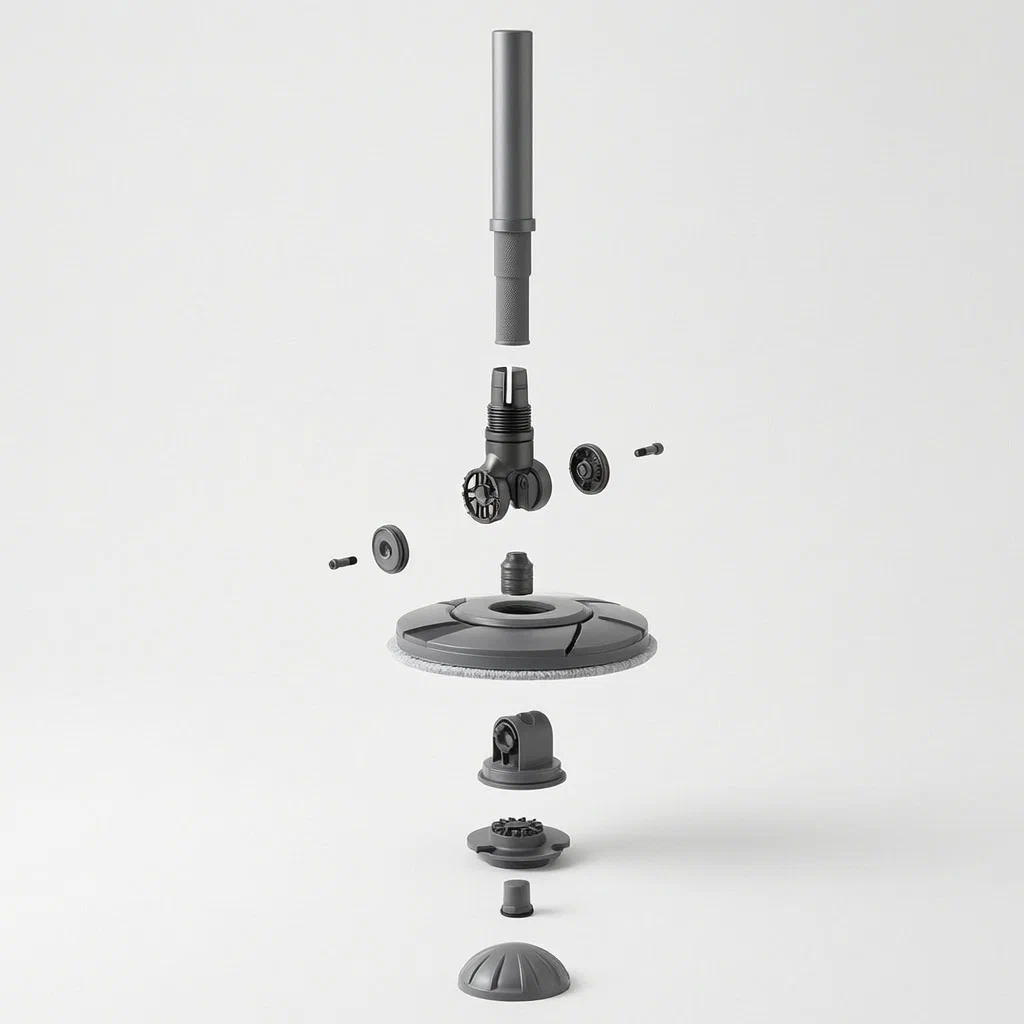
Splat! What let you down?
🔄
Ratchet Rotation
Active and driven ratchets convert upward rod movement into single-direction disc spin.
📏
Compact Design
The twist rod and mop disc are close together, reducing the need for long-range lifting.
🧱
Fixed Interface
Includes a connection piece and rotary head setup for stable vertical orientation.
🛡️
Secure Assembly
A fall-prevention cap secures the internal movable parts and driven member.
Bring this product to market
- ✓ Patent vetted China-only family and legal status checked
- 2 Product brief · now How it works, uses and options written up
- 3 Prototype First samples for buyers to review
- 4 Pilot run Small first batch for launch customers
- 5 Volume production Repeat orders at scale
Buyer interest
– of 100 buyers needed to start prototyping
One click, no sign-up. Each vote is one real visitor, and products with the most interest go to prototyping first.
Build team: no members yet. Need a partner, co-funding or skills to build this? Join and we introduce the team once it forms.
The problem
Many manual spin mops rely on friction or complex gear trains that require significant force or wide arm movements to activate. Users often have to lift the handle high or twist their wrists aggressively to get the mop head to spin effectively. This can cause fatigue during extended cleaning sessions. Additionally, if the driving mechanism is too bulky, it interferes with the low-angle reach needed under furniture. There is a need for a simpler mechanical linkage that translates basic vertical strokes into effective rotation without demanding excessive range of motion from the user.
The solution
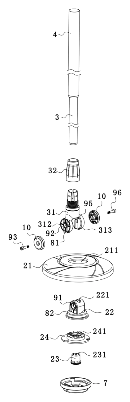
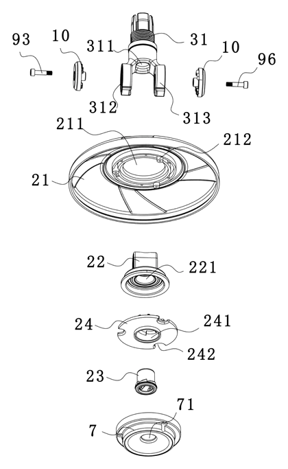
- Mop Head Structure: The assembly consists of a mop disc (21), a rotary head (22), a rotatable movable part (23), and a driven member (24). These components are housed within the head casing.
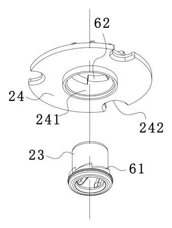
- Unidirectional Spline (Ratchet): The core innovation is a ratchet mechanism. An active ratchet (61) is set on the movable part (23), while a driven ratchet (62) interacts with it.
- Engagement Logic: When the movable part (23) moves upwards, the active ratchet (61) engages with the driven ratchet (62). This engagement creates a unidirectional rotation stop, forcing the connected components to turn in a specific direction.
- Rod Connection: The mop rod includes an inner bar and an outer bar. The lower end of the inner bar has a connection piece (31) that cooperates with the rotary head (22) to maintain vertical orientation while allowing the spin action.
- Stabilization: A fall-prevention cap (7) screws onto the bottom of the mop disc to hold the rotary head, movable part, and driven member in place, ensuring they function as a cohesive unit.
Who it is for
- Household Cleaning Brands: Companies looking to differentiate their spin mops by offering a mechanism that requires less wrist strain and smaller vertical strokes.
- Commercial Cleaning Suppliers: Businesses providing equipment for janitorial staff who need durable, simple mechanisms that withstand frequent use without complex maintenance.
- Amazon Sellers: Private label brands seeking unique selling points like “easy spin” or “low-lift operation” to compete against generic spin mops.
- Manufacturers of Cleaning Accessories: Factories specializing in plastic molding and small mechanical assemblies that want to produce heads compatible with existing standard mop rods.
How it works
The main parts
| No. | Part | What it does |
|---|---|---|
| 21 | Mop Disc | The base plate holding the microfiber strands; contains openings for the rotary head. |
| 22 | Rotary Head | Connects the rod to the disc; rotates independently of the disc unless driven. |
| 23 | Movable Part | A sleeve or component that moves vertically; carries the active ratchet teeth. |
| 24 | Driven Member | Located below the rotary head; carries the driven ratchet teeth to receive motion. |
| 61 | Active Ratchet | Teeth on the movable part (23) that engage when moving up. |
| 62 | Driven Ratchet | Teeth on the driven member (24) that mesh with the active ratchet. |
| 31 | Connection Piece | Links the inner rod to the rotary head, maintaining alignment. |
| 7 | Fall Prevention Cap | Screws onto the bottom to secure all internal moving parts. |
Operating Steps
- Insert Rod: The inner bar of the mop rod connects to the rotary head (22) via the connection piece (31).
- Upward Stroke: The user pushes the handle upward. This causes the movable part (23) inside the head to move up relative to the stationary components.
- Ratchet Engagement: As the movable part rises, the active ratchet (61) catches against the driven ratchet (62). Because of the tooth geometry, this slip-free engagement forces the driven member and subsequently the mop disc (21) to rotate in a single direction.
- Return Stroke: When the user pulls the handle down, the ratchets disengage or slide over each other freely, resetting the position without reversing the disc’s spin.
- Repeat: Rapid up-and-down pumping motions create continuous rotation, wringing out water or polishing the floor depending on the attachment used.
Applications
Daily Floor Wiping
In home environments, users can clean large areas of tile or laminate flooring by simply pumping the handle up and down. The ratchet mechanism ensures the mop spins consistently, removing dirt and drying the floor faster than static wiping, without requiring the user to bend or twist excessively.
Under-Furniture Reach
Because the drive mechanism is compact and the distance between the twist rod and the mop disc is short, the head can tilt deeply under beds and sofas. The low-profile internal gears allow the joint to remain slim, facilitating access to tight spaces where bulkier spin mechanisms would not fit.
Commercial Janitorial Tasks
Janitors in offices or retail stores benefit from the reduced physical strain. The mechanism allows for quick spot-cleaning or rinsing cycles without needing a bucket-based wringer immediately. The simplicity of the two-part ratchet reduces failure points compared to complex gear trains, making it suitable for high-frequency professional use.
Wet Mopping and Drying
The consistent rotation generated by the upward stroke helps distribute water evenly during wet mopping or accelerates evaporation during dry buffing. The unidirectional nature prevents the mop from tangling or winding around the rod, which can happen with bidirectional friction drives.
Where it is less suitable
- Heavy-Duty Industrial Scrubbing: The plastic ratchet teeth may wear out under extreme torque required for stripping wax or scrubbing concrete; metal-gear industrial machines are better for those tasks.
- Very Small Spaces: While compact, the need for vertical clearance to pump the handle means it cannot be used in closets or rooms with ceilings lower than the rod length plus stroke height.
- High-Speed Automatic Wringers: This is a manual drive system. It does not replace electric spin buckets that achieve higher RPMs through motors.
Frequently asked questions
How does this mop spin without twisting my wrist?
The patent describes a mechanism where the user moves the handle vertically (up and down). Inside the head, a movable part with an active ratchet moves up and engages with a driven ratchet. This converts the vertical motion directly into rotational force for the mop disc, eliminating the need for circular wrist movements.
Is the patent still active?
No. The patent CN208876424U is a Chinese utility model that lapsed on August 17, 2021, due to non-payment of annual fees. It was never filed outside of China.
Can I use this head with any standard mop rod?
The design includes a specific connection piece (31) and rotary head (22) interface. To work with existing rods, you must manufacture the connection piece to match the thread or snap-fit standard of your chosen rod supplier. It is not inherently universal without adaptation.
What materials are recommended for the ratchet teeth?
The patent does not specify exact materials. However, for durability against repeated engagement, engineering plastics like POM (Polyoxymethylene) or reinforced Nylon are typically used in similar applications to reduce wear and noise.
Does it work for both wet mopping and dry sweeping?
Yes. The mechanism provides rotation regardless of whether the fibers are wet or dry. The speed of rotation depends on the frequency and force of the user’s upward strokes.
Why is there a “fall prevention cap”?
The cap (7) screws onto the bottom of the mop disc to secure the internal components (rotary head, movable part, driven member) in place. Without it, the loose parts could fall out during use or transport.
Can this design be made and sold in the US?
Yes. Since the patent lapsed and had no international counterparts, the specific design described in CN208876424U is in the public domain. However, you should verify that your specific implementation does not infringe on other active US patents in the spin mop category.
Are you affiliated with the patent owner?
No. IP2M is an independent design and manufacturing service working from the public patent document.
Request a quote
Click Request a Quote below to see our email address - copy it, or open your email app with a ready-made message. Please mention patent CN208876424U in the subject.
Helpful details to include:
- Your company and channel (cleaning brand, retailer, Amazon seller)
- Target rod compatibility (thread size, diameter, or proprietary lock)
- Mop disc diameter and fiber type preference
- Material requirements for the internal mechanism
- Estimated quantity and target price
- Timeline - when you would like samples and the first shipment
You can also reach us at (332) 203-9997.
Explore this product
Interested in building this?
Tell us your target market, quantity and timeline. We reply with options for prototyping, small-batch runs or volume production.
Send your inquiry to
Please put CN208876424U in the subject line and tell us your company, country, estimated quantity and timeline.
Prefer to talk? Call (332) 203-9997.
More product-ready patents
All Home, Kitchen & Cleaning patents →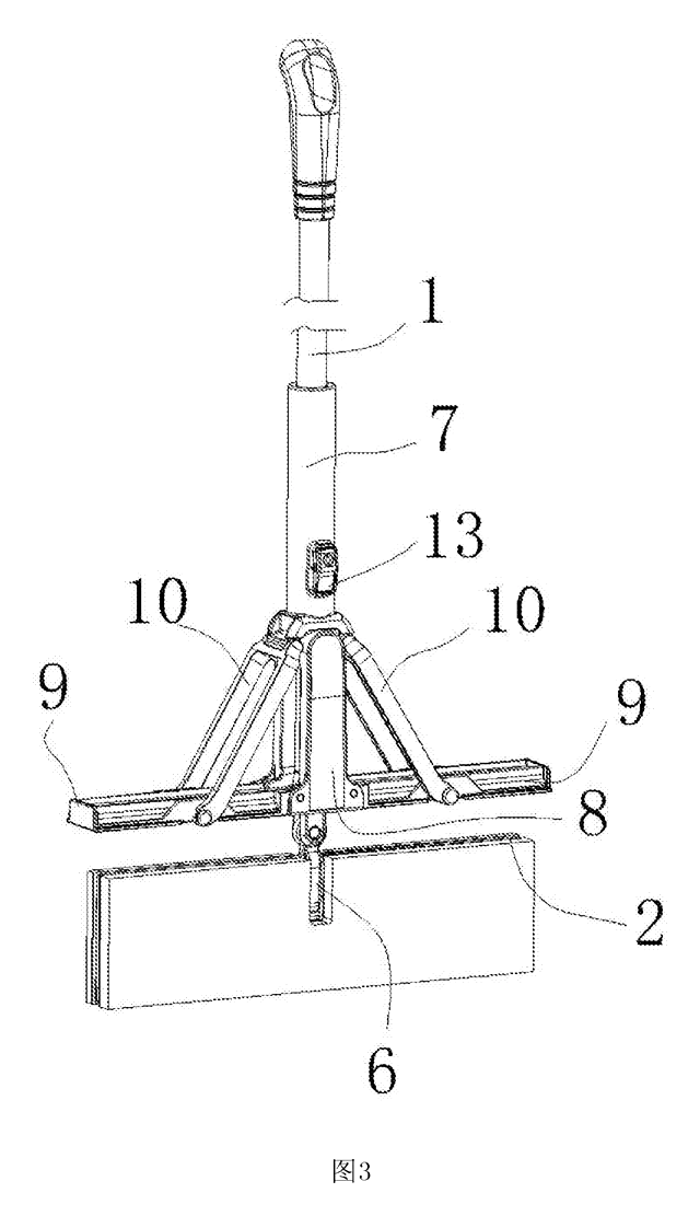
Home, Kitchen & Cleaning
Self-Wringing Flat Mop with Fold-Away Wringer
Flat mop with a built-in wringer that opens only when you wring and folds flat against the pole when you mop.
Patent CN207734114U
Home, Kitchen & Cleaning
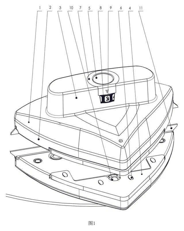
Magnetic Double-Sided Window Cleaner with Dial-Set Magnet Strength
Magnetic window cleaner with a sealed, sliding magnet, dial-set strength for different glass thicknesses and a spring-held idle position.
Patent CN209360543U
Home, Kitchen & Cleaning
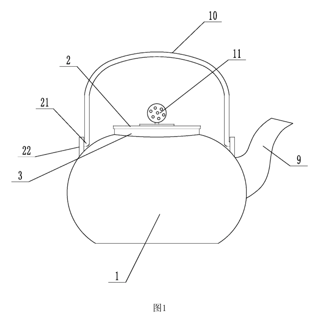
Metal Kettle with Magnetic Lid That Stays On When Pouring
Metal teapot/kettle with a magnet-held lid that does not fall off when pouring, and an insulated, vented lid knob.
Patent CN210540477U
Home, Kitchen & Cleaning
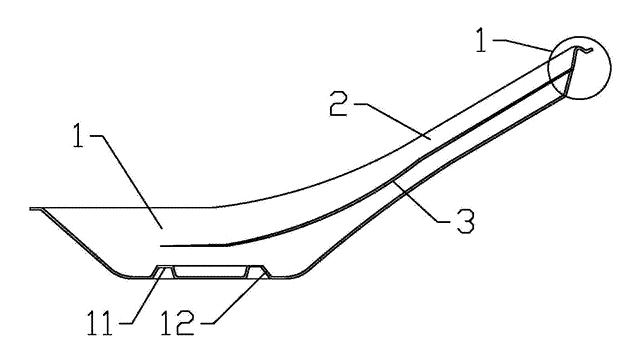
Reinforced Disposable Soup Spoon
Disposable soup spoon with a handle-to-bowl rib, stiffened edges and a ring foot to resist breaking.
Patent CN206964482U
Home, Kitchen & Cleaning
Self-Switching Double-Squeegee Window Cleaner
Cleaning head with two squeegee blades that switch automatically with the direction of movement.
Patent CN212630655U
Home, Kitchen & Cleaning
Self-Rinsing Roller Scrub Brush with Dirty-Water Tank
Powered roller brush that rinses and spins its bristles clean inside the body and stores the dirty water.
Patent CN210076909U
Browse by category
- Apparel & Accessories (28)
- Baby & Kids (20)
- Bags & Luggage (12)
- Bath & Personal Care (21)
- Car Accessories (16)
- Furniture, Bedding & Storage (15)
- Garden & Outdoor (21)
- Health & Wellness (10)
- Home, Kitchen & Cleaning (32)
- Lighting (15)
- Packaging & Containers (8)
- Pet Products (7)
- Phone & Camera Accessories (5)
- Retail Display (16)
- School, Office & Art (22)
- Sports & Recreation (30)
- Tools & Workshop (36)
- Toys & Games (15)
This page is based on the public patent document CN208876424U, assigned to Individual. IP2M is an independent manufacturing service and is not affiliated with, endorsed by or licensed by the patent owner. Images marked as concept renderings are illustrations, not photos of an existing product. Patent status information is provided for reference only and is not legal advice; confirm freedom to operate for your market before production. Full disclaimer.