At a glance
| Patent number | CN209600696U (application CN201920316133) |
| Type | China utility model (实用新型) - protects product shape and structure |
| Original title | Bicycle bottle cage with tool set (具工具组的自行车水壶架) |
| Patent owner | Naixing Vehicle Material Shenzhen Co ltd, Zhangzhou Anjiayi Industrial Co ltd, Naixing Enterprise Co ltd |
| Inventors | Shi Heren, Wang Benli, Yang Xinhuan |
| Filing date | 2019-03-13 |
| Grant date | 2019-11-08 |
| Status (China) | In force in China until at most 2029-03-13 (if annual fees are paid) |
| Patent family | Chinese filings only - no US, European, Japanese, PCT or other filings listed |
| Cited by | 5 later documents |
| Source | Google Patents (search for CN209600696U) |
What the claims cover, in plain language
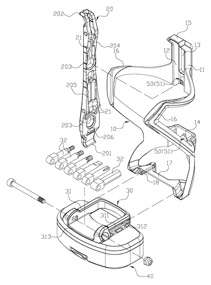
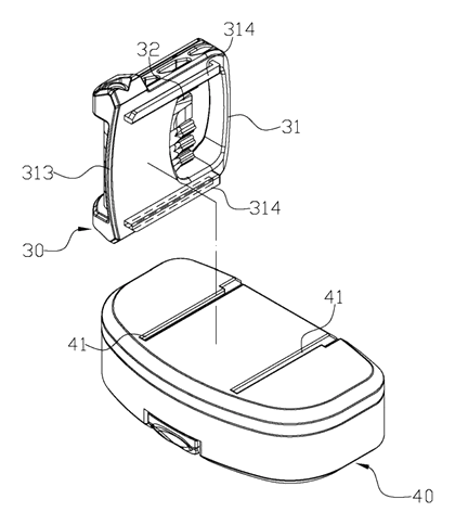
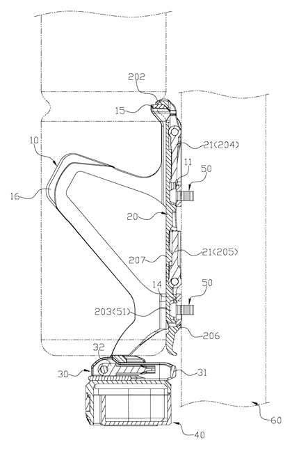
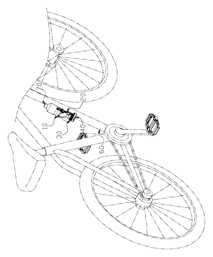
Claim 1 describes a bicycle bottle cage assembly including a cage, a tire lever, and a screwdriver tool set. The cage has a back plate with an indented accommodating space, a hollow portion, and combined holes for bolts. The top edge bends forward into a supporting portion, and two side stop portions connect at a bottom edge that features a first joining section. The tire lever has a working end, a hook-shaped fixed end, a snap-fit recess, and two containing grooves on its back side. Wrench tool rods sit in these grooves. The lever indents into the accommodating space, the snap-fit recess catches the bolt head, and the hook-shaped end rests on the supporting portion. The screwdriver tool set has a handle with a second joining section that fixes to the first joining section on the cage, and a pivot group holding multiple screwdriver tool heads that rotate outward.
Claim 2 specifies the back plate is divided into upper and lower sections connected by the side stop portions. Claim 3 states the combined hole is a long hole allowing vertical adjustment. Claim 4 defines the first and second joining sections as a matched rail bar and track slot, with a protrusion in the track slot. Claim 5 adds a button block extending from the tire lever’s back side to clasp the bottom edge of the back plate. Claim 6 notes the tire lever includes a pressing portion.
This is a simplified reading for orientation only. The legal scope is defined by the exact claim wording in the official Chinese document.
What this means for US production
This patent was filed only in China and is currently in force in China until at most 2029-03-13 (if annual fees are paid). It has no US or other foreign counterpart. Because it is active in China, making or selling this specific bottle cage design in China needs the owner’s permission.
Two points to settle early:
- Other patents may exist. Several US design patents citing this Chinese utility model have been granted to Jian Yang (USD1047874S1), Lian Wang (USD1065016S1), Team Howly, LLC (USD1068626S1), and AteamProducts LLC (USD1078589S1). These entities hold later US design rights in the bicycle bottle cage and tool integration field. A freedom-to-operate (FTO) review covering both utility and design patents is necessary before launching sales in the US.
- Joining mechanism tolerances. The rail bar, track slot, and snap-fit recess rely on precise dimensions to hold the tools firmly during vibration. Mold shrinkage and material flexibility must be calculated early so the tools do not loosen on rough roads or become too tight to remove.
Customization and manufacturing
What can be customized
| Area | Options |
|---|---|
| Material | Nylon, glass-filled nylon, polycarbonate, or aluminum for the cage; POM or steel for tools |
| Color | Any molded or anodized color to match brand palettes |
| Tool selection | Number and sizes of wrench tool rods; types of screwdriver tool heads on the pivot group |
| Joining mechanism | Dimensions of the rail bar and track slot to be confirmed in design |
| Mounting holes | Standard spacing, or elongated slots for adjustable positioning |
| Branding | Molded logos on the back plate or side stop portions |
Things to plan for (US market)
- CPSC 16 CFR 1512 - applies to complete bicycles; if the cage is sold fitted to a bike, it must not create sharp edges or protrusions that break the rule’s edge and protrusion requirements.
- California Proposition 65 - plastics, paints, and metal alloys must be screened for listed chemicals.
How a project runs
- Inquiry - target materials, tool configurations, colors, and estimated volumes.
- Design - CAD modeling of the cage, snap-fit recess, rail bar/track slot, and pivot group; tolerance analysis for vibration retention.
- Prototype - 3D printed or CNC machined samples to verify the fit of the tire lever, wrench rods, and screwdriver handle.
- Pilot run - injection molding or die casting of initial units; vibration and drop tests simulating road conditions.
- Production - full-scale molding, tool stamping or machining, assembly of the pivot group, and packaging.
Quantities & timeline
The cage body requires an injection mold (for plastics) or a die-casting mold (for metals). The tire lever and wrench rods need separate stamping dies or molds. The screwdriver pivot group involves small precision components. Vibration testing to ensure the snap-fit recess and joining sections hold under load takes significant development time. Certification screening for US retail requirements follows pilot validation. Send us your material preferences, tool configuration, quantity and target price and we will reply with options.
Patent drawings
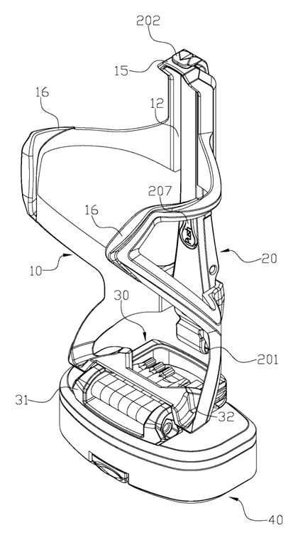
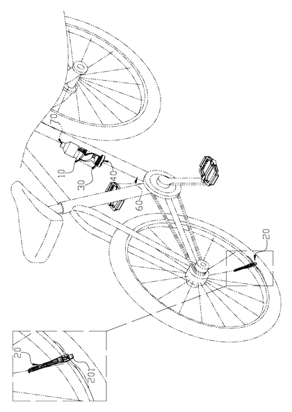
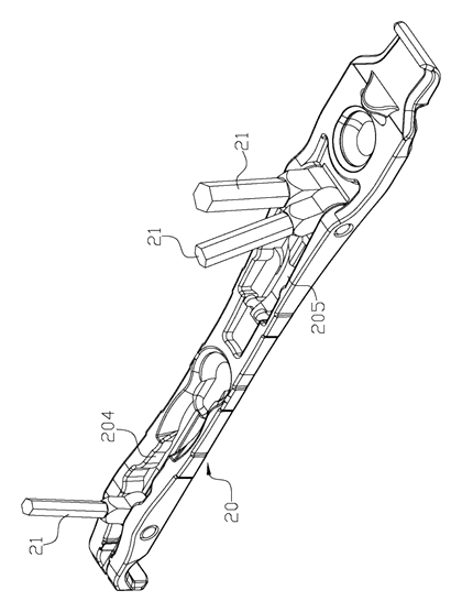
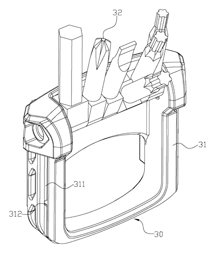
Drawings reproduced from the public patent document for reference.