
Patent CN209647665U
Updated November 6, 2026Electric Hand Drill with Integrated Magnetic Scrap Collection
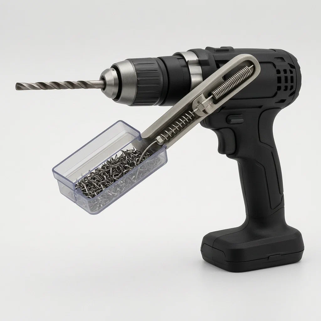
Standard drills scatter metal chips everywhere, creating slip hazards and clogging threads. This patent describes a drill with an integrated magnetic collection system. A movable bracket attaches near the chuck, holding a storage box lined with electromagnet posts. When powered, these posts attract ferrous debris directly into the container. The bracket slides along a clamping groove to stay positioned under the bit as the hole deepens, ensuring continuous capture without manual intervention.
- China utility model - lapsed
- No filings outside China
- Power tool accessories
- Electromagnet posts, sliding bracket, integrated storage
Splat! What let you down?
🧲
Electromagnetic Capture
Storage box contains electromagnet posts that attract metal shavings during drilling.
📏
Sliding Bracket
The collector moves along a clamping groove to stay aligned with the drill bit depth.
🔋
Integrated Power
Spring-loaded contacts in the groove transfer power from the drill battery to the magnets.
🗑️
Detachable Storage
The collection box interacts with the bracket for easy removal and cleaning.
Bring this product to market
- ✓ Patent review Patent family and legal status reviewed in the relevant jurisdictions.
- 2 Product brief · now How it works, uses and options written up
- 3 Prototype First samples for buyers to review
- 4 Pilot run Small first batch for launch customers
- 5 Volume production Repeat orders at scale
Buyer interest
– of 100 buyers needed to start prototyping
One click, no sign-up. Each vote is one real visitor, and products with the most interest go to prototyping first.
Build team: no members yet. Need a partner, co-funding or skills to build this? Join and we introduce the team once it forms.
Patent Rights & Team Participation
Before joining a development team, participants should ensure they have the necessary rights or authorization to participate in the project.
Participation is generally appropriate where:
- You own the relevant patent rights or have obtained permission or a license from the rights holder.
- The relevant patent rights have expired or have been legally invalidated in the jurisdictions where the planned activities will take place.
- The planned development, manufacturing, and commercialization activities have been independently assessed and do not infringe applicable patent rights in the relevant jurisdictions.
Important: Being located outside a country where a patent is protected does not automatically exempt you from patent infringement risks. Patent rights may apply based on where development, manufacturing, use, sale, or import activities take place.
IP2M does not grant any patent license or authorization through team participation. Joining a project does not provide permission to use, manufacture, or commercialize patented technology.
The problem
When drilling into metal, wood, or composite materials, debris flies off at high speed. For metal, this creates sharp, hot chips that can injure operators, damage surfaces, or jam machinery. Standard drills do not contain this waste; users must stop frequently to clear jams or risk inhaling dust. Existing vacuum attachments are bulky, require separate hoses, and often lack the suction power to lift heavy steel chips. There is a need for a compact solution that captures ferrous debris directly at the point of contact without external air lines.
The solution
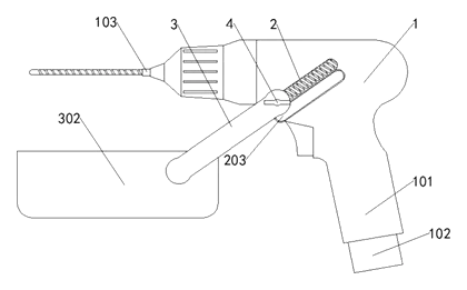
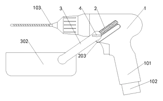
This patent describes an electric hand drill modified with a dedicated scrap collection assembly. The core components are:
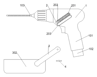
- Apparatus Main Body (1): Includes the standard Handle (101), Battery (102), and Drill Bit (103).
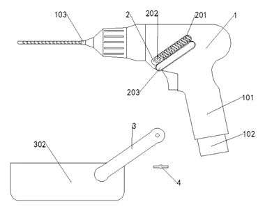
- Clamping Groove (2): Located on the front-end surface of the main body. It contains a Spring (201) and a Converting Interface (202).
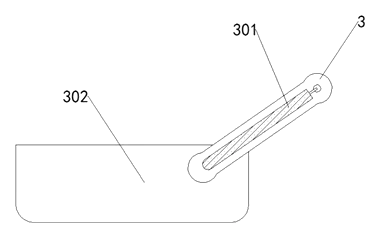
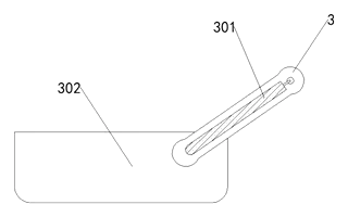
- Bracket (3): Attaches to the Converting Interface. It features a Winding Displacement (301) internally and connects to the Storage Box (302).
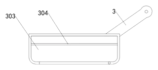
- Storage Box (302): Contains an Inside Groove (303) fitted with multiple Electromagnet Posts (304).
- Fixed Conductive Nail (4): Secures the bracket to the main body.
The bracket slides along the clamping groove. As the drill bit penetrates deeper, the operator adjusts the bracket’s position so the storage box remains directly beneath the bit tip. The electromagnets are powered by the drill’s battery via conductive elements in the spring and groove, attracting metal chips into the box.
Who it is for
- Industrial Maintenance Teams: Technicians who drill into steel structures and need to prevent chip scattering in sensitive environments like food processing plants or server rooms.
- Automotive Repair Shops: Mechanics working on engine blocks or chassis where loose metal fragments can cause catastrophic failure if left behind.
- Metal Fabrication Workshops: Small-to-medium shops producing custom parts where cleanliness and safety are priority concerns.
- DIY Enthusiasts and Homeowners: Users seeking a safer, cleaner way to perform home repairs involving metal studs or pipes without buying expensive industrial vacuums.
How it works
The main parts
| No. | Part | Function |
|---|---|---|
| 1 | Apparatus Main Body | Houses the motor, handle, and battery. |
| 2, 201 | Clamping Groove & Spring | Allows vertical movement of the bracket; transmits electrical current. |
| 202 | Converting Interface | Connects the bracket to the main body. |
| 3 | Bracket | Structural support for the storage unit; slides on the groove. |
| 302 | Storage Box | Container for collected debris. |
| 303 | Inside Groove | Housing for the electromagnets within the box. |
| 304 | Electromagnet Posts | Generate magnetic field to attract ferrous chips. |
| 4 | Fixed Conductive Nail | Secures the bracket assembly to the drill body. |
Operating Steps
- Assembly: Attach the Bracket (3) to the Converting Interface (202) on the drill’s front face. The Fixed Conductive Nail (4) locks it in place.
- Positioning: Slide the bracket down the Clamping Groove (2) so the Storage Box (302) sits just below the Drill Bit (103).
- Activation: Turn on the drill. Current flows from the Battery (102) through the Spring (201) and Winding Displacement (301) to the Electromagnet Posts (304).
- Collection: As the bit cuts material, metal shavings are generated. The active magnets attract these ferrous particles into the Storage Box.
- Adjustment: As the hole deepens, slide the bracket further down to maintain proximity to the cutting edge.
- Cleanup: Once finished, turn off the drill (deactivating magnets) and remove the Storage Box (302) to empty the collected chips.
Applications
Metal Stud Framing
Contractors drilling holes in steel studs for plumbing or wiring can keep the floor area free of hazardous, sharp chips. The magnetic collection prevents debris from falling into wall cavities, reducing cleanup time significantly between floors.
Automotive Chassis Work
Mechanics removing bolts or drilling access holes in vehicle frames benefit from contained debris. Loose metal fragments can interfere with brake lines or suspension components; this attachment ensures they are captured immediately rather than scattering onto the shop floor.
Machinery Maintenance
In factories, drilling into machine beds or housings requires strict cleanliness to protect moving parts. This tool allows technicians to perform minor repairs without halting production for extensive vacuuming, as the magnets hold the chips securely in the box.
DIY Home Renovation
Homeowners installing shelving into metal beams or pipe supports often struggle with cleanup. The integrated system makes the task less messy and safer for families, avoiding the need to rent specialized equipment for small jobs.
Where it is less suitable
- Non-Ferrous Materials: Aluminum, copper, brass, and wood chips are not magnetic. The electromagnets will not attract them, rendering the collection feature ineffective for these materials.
- Deep Hole Drilling: If the hole is very deep, the bracket may need frequent adjustment to stay close to the bit tip, which can be cumbersome compared to fixed nozzle systems.
- High-Volume Production Lines: Automated CNC machines typically use coolant flushes and industrial vacuums; this handheld attachment is designed for manual, intermittent use.
Patent & Production
At a glance
| Patent number | CN209647665U (application CN201920513557) |
| Type | China utility model (实用新型) - protects product shape and structure |
| Original title | Electric hand drill with scrap collection function (一种具有铁屑收集功能的手电钻) |
| Patent owner | Individual |
| Inventors | Li Jiantao |
| Filing date | 2019-04-16 |
| Grant date | 2019-11-19 |
| Status (China) | Lapsed - terminated for non-payment of annual fees (recorded 2023-03-24) |
| Patent family | Public record shows Chinese filings only - no US, European, Japanese, PCT or other filings listed |
| Cited by | 3 later documents |
| Source | Google Patents (search for CN209647665U) |
What the claims cover, in plain language
Claim 1 defines an electric hand drill comprising an apparatus main body, handle, battery, and drill bit. Key structural features include a clamping groove on the front surface containing a spring and converting interface. A bracket attaches via this interface and holds a storage box. Inside the box, an inner groove houses electromagnet posts. A fixed conductive nail secures the bracket to the main body.
Claim 2 specifies that the clamping groove and spring are inclined, allowing the bracket to slide while maintaining electrical contact. Claim 3 details that a live wire fits closely inside the spring and connects electrically to the converting interface, powering the electromagnets. Claim 4 adds a rubber pad around the fixed conductive nail and notes the nail passes through the bracket. Claim 5 states that multiple electromagnet posts are distributed with gaps between them. Claim 6 describes an open plate at the bottom of the inner groove, arranged for activity (likely for dumping chips). Claim 7 confirms the battery, converting interface, winding displacement, and electromagnet posts are electrically connected to a control switch.
This is a simplified reading for orientation only. The legal scope is defined by the exact claim wording in the official Chinese document.
What this means for US production
This patent was filed in China and has lapsed due to non-payment of annual fees, meaning it no longer restricts anyone in China either. The public record shows no US or other foreign counterpart.
Two points to settle early:
- Other patents may exist. Power tools and accessories are heavily patented fields. While this specific configuration appears unique in the public record, broader concepts of magnetic debris collection or sliding tool attachments may be covered by existing US patents held by major tool manufacturers. A freedom-to-operate (FTO) review is recommended before mass production.
- Electrical Safety Standards. Since the design involves routing electricity from the battery to an accessory via mechanical contacts, compliance with UL standards for cordless tools and accessories is critical.
Customization and manufacturing
What can be customized
| Area | Options |
|---|---|
| Magnet Strength | Number and grade of electromagnet posts based on expected chip weight. |
| Box Capacity | Size of the storage box for different job durations. |
| Mounting Fit | Adapt the clamping groove and interface to fit various drill body diameters. |
| Release Mechanism | Design of the open plate (claim 6) for easier dumping. |
| Materials | Heat-resistant plastics for the box; stainless steel for springs. |
Things to plan for (US market)
- UL 62841 / IEC 62841: Standards for motor-operated electric tools. Any accessory affecting the tool’s electrical path must meet insulation and creepage requirements.
- OSHA Guidelines: Workplace safety regulations regarding flying debris and magnetized tools near pacemakers or sensitive electronics.
- Battery Compatibility: Ensuring the voltage draw from the electromagnets does not overload the drill’s battery circuitry.
How a project runs
- Inquiry - Define target drill models and capacity needs.
- Design - Engineer the mounting interface, magnet array, and electrical contacts.
- Prototype - Create functional samples to test magnetic retention force and electrical reliability.
- Testing - Verify durability of the sliding mechanism and safety of the electrical connections.
- Production - Mold plastic parts, wind coils, assemble brackets, and integrate with packaging.
Quantities & timeline
Tooling for injection molded parts and precision stamping for the spring contacts will take several weeks. Assembly involves manual winding of electromagnet coils or sourcing pre-made modules. Certification testing for electrical safety adds time to the launch schedule. Send us your target drill compatibility list, required collection volume, and estimated quantity and we will reply with options.
Production notes
Tooling and process
Likely uses glass-filled nylon injection molding for the storage box and bracket to withstand impact and heat. Stamped steel is typical for the spring and conductive nails. Machining may be needed for precise fitting of the converting interface.
Cost drivers
Material and heat treatment costs typically depend on the grade of steel used for the spring contacts. The number of stamping dies increases with complex profile shapes. Surface finish on the bracket affects friction during sliding.
Prototyping path
Typically, start with a 3D-printed handle and bracket to check ergonomics. Use machined or off-the-shelf blade components for initial tests. Functional samples should verify the magnetic pull strength against realistic chip loads.
What we would change before tooling
We would likely need to ensure the rubber pad on the conductive nail provides sufficient grip to prevent vibration loosening. Adjust the gap between electromagnet posts to maximize coverage without short-circuiting.
Common failure points
Spring fatigue and rate consistency are critical; a weak spring breaks electrical contact. Magnet grade and retention may fail if chips are too heavy or wet. Coating wear on the sliding groove could increase friction over time.
Patent drawings
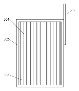
Drawings reproduced from the public patent document for reference.
Frequently asked questions
How does the collector attach to my drill?
It uses a clamping groove and converting interface on the front of the drill body. The bracket slides onto this interface and is secured by a fixed conductive nail. This design assumes the drill has a compatible mounting surface or adapter.
Does it work on aluminum or wood?
No. The collection relies on electromagnet posts, which only attract ferrous metals like steel and iron. Wood chips, aluminum, and plastic will fall out of the box unless physically blocked.
How is the electromagnet powered?
The patent describes a live wire fitted inside the spring within the clamping groove. This wire connects to the drill’s battery via the converting interface. When the drill is on, current flows to the magnets.
Can I adjust the height of the collector?
Yes. The bracket slides along the inclined clamping groove. You can move it up or down to keep the storage box close to the drill bit as you go deeper into the material.
Is there a risk of electric shock?
The design integrates electrical contacts into the mechanical sliding mechanism. Proper insulation and adherence to tool safety standards are essential to prevent shorts or shocks, especially if the groove gets dirty or damaged.
How do I empty the collected chips?
The patent mentions an open plate at the bottom of the inner groove. Turning off the drill deactivates the magnets, allowing chips to fall through the open plate into a bin or trash bag.
Can this design be made and sold in the US?
The patent was filed in China and has lapsed, and the public record shows no US counterpart, so it does not restrict the design in the US or in China. However, power tool accessories are subject to strict safety certifications (like UL), and other broad patents may apply. We recommend a freedom-to-operate check before volume production.
Are you affiliated with the patent owner?
No. IP2M is an independent design and manufacturing service working from the public patent document.
Request a quote
Click Request a Quote below to see our email address - copy it, or open your email app with a ready-made message. Please mention patent CN209647665U in the subject.
Helpful details to include:
- Your company and channel (tool brand, workshop supplier, industrial distributor)
- Target drill models (voltage, diameter, mounting constraints)
- Capacity requirements (size of storage box)
- Estimated quantity and target price
- Timeline - when you would like samples and the first shipment
You can also reach us at (332) 203-9997.
Page editor: Daniel Chen, Product Research Editor · IP2M
Last updated November 6, 2026. If something on this page looks wrong, email [email protected] and we will check it against the patent.
Interested in building this?
Tell us your target market, quantity and timeline. We reply with options for prototyping, small-batch runs or volume production.
Send your inquiry to
Please put CN209647665U in the subject line and tell us your company, country, estimated quantity and timeline.
Prefer to talk? Call (332) 203-9997.
More product-ready patents
All Tools & Workshop patents →
Tools & Workshop
Rolling Tool Box with Telescoping Step Ladder
Telescoping A-frame ladder with an attached rolling tool box that slides to your working height.
Patent CN206290197U
Tools & Workshop
Folding 3-Handle Wrench Multi-Tool
Folding three-handle wrench multi-tool with magnetic screwdriver bits, saw, file and bottle opener.
Patent CN205290875U
Tools & Workshop
Rolling Auto-Repair Tool Cabinet with Built-In Lights
Lockable rolling tool cabinet for car repair with interior lights, a lubricant tray, parts drawers and a tool bay.
Patent CN205989314U
Tools & Workshop
Wide-Opening Folding Bolt Cutter
Bolt cutter with linked, gear-meshing handles that open up to 190° and fold in half for storage.
Patent CN207206226U
Tools & Workshop
Nail-Holding Hammer with Fold-Out Drivers
Hammer with a nail-holding T-slot in the head and fold-out drivers stored in the handle.
Patent CN205254927U
Tools & Workshop
Modular Wrench with Screw-On Heads
Wrench handle with a three-way threaded hub for screw-on adjustable and hex heads, plus a pipe sleeve.
Patent CN206216564U
Browse by category
- Apparel & Accessories (44)
- Baby & Kids (28)
- Bags & Luggage (16)
- Bath & Personal Care (29)
- Car Accessories (23)
- Furniture, Bedding & Storage (23)
- Garden & Outdoor (31)
- Health & Wellness (13)
- Home, Kitchen & Cleaning (47)
- Lighting (22)
- Packaging & Containers (11)
- Pet Products (11)
- Phone & Camera Accessories (9)
- Retail Display (24)
- School, Office & Art (33)
- Sports & Recreation (43)
- Tools & Workshop (51)
- Toys & Games (21)
This page is based on the public patent document CN209647665U, assigned to Individual. IP2M is an independent manufacturing service and is not affiliated with, endorsed by or licensed by the patent owner. Images marked as concept renderings are illustrations, not photos of an existing product. Patent status information is provided for reference only and is not legal advice; confirm freedom to operate for your market before production. Full disclaimer.