
Patent CN210672684U
Updated October 28, 2026Three-Section Gear-Synchronized Drawer Slide Rail Assembly
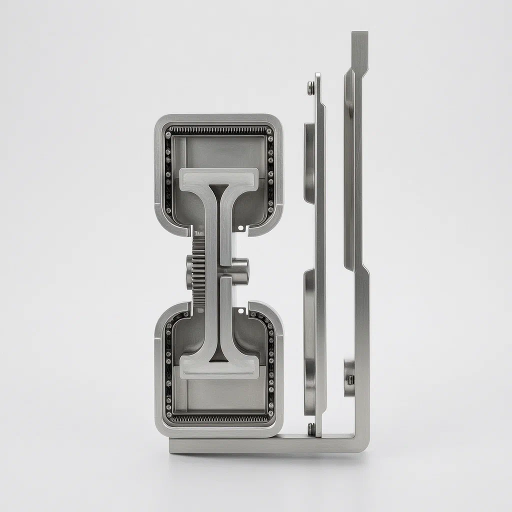
Standard three-section drawer slides rely on sliding friction between the rails, which can create noise and uneven movement as the sections extend. This assembly replaces that friction with a gear-driven system. A gear mounted on the middle rail meshes with an upper rack on the upper retainer and a lower rack on the lower retainer. When the movable rail is pulled, the gear drives the middle rail along the fixed rail in a controlled motion. The retainers are shaped like door frames and carry rows of rollers and balls that run against the flat plates and the concave arc transitions of the rails. The fixed rail uses a separate support end welded to an L-shaped connecting end, providing a rigid mounting point for the cabinet.
- China utility model - in force
- No filings outside China
- Cabinet & furniture hardware
- Steel rails, gear and rack drive, roller and ball retainers
Splat! What let you down?
⚙️
Gear-driven middle rail
A gear on the middle rail meshes with upper and lower racks to move the sections together.
🔇
Reduced sliding friction
The gear transmission eliminates sliding friction between the rails, reducing noise.
🛞
Roller and ball retainers
Door-frame retainers carry rows of rollers and balls running on flat plates and arc transitions.
📐
Arc-transition middle rail
The middle rail bends use inwardly concave arc transitions to guide the balls smoothly.
Bring this product to market
- ✓ Patent vetted China-only family and legal status checked
- 2 Product brief · now How it works, uses and options written up
- 3 Prototype First samples for buyers to review
- 4 Pilot run Small first batch for launch customers
- 5 Volume production Repeat orders at scale
Buyer interest
– of 100 buyers needed to start prototyping
One click, no sign-up. Each vote is one real visitor, and products with the most interest go to prototyping first.
Build team: no members yet. Need a partner, co-funding or skills to build this? Join and we introduce the team once it forms.
The problem
In conventional three-section drawer slides, the middle rail moves relative to the fixed rail through direct sliding contact. This sliding friction generates noise and can cause the rails to bind or move unevenly, especially when the drawer carries weight. The sections may not extend in a coordinated manner, leading to a jerky feel when opening or closing the drawer. Over time, the friction wears the contact surfaces, changing the clearance between the rails and affecting the drawer’s alignment within the cabinet.
The solution
This assembly introduces a gear-driven mechanism to coordinate the movement of the three rails.
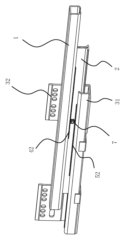
- The movable rail (1) connects to the drawer side plate and rests on the middle rail.
- An upper retainer (4) sits between the movable rail and the middle rail. Its lower end carries a downward-facing upper rack (42).
- A lower retainer (5) sits between the middle rail and the fixed rail (3). Its upper end carries an upward-facing lower rack (52).
- A gear (7) is rotatably connected to the middle rail (2) and meshes with both the upper rack and the lower rack.
- When the movable rail is pulled, the gear turns and drives the middle rail along the fixed rail through the meshing racks, replacing sliding friction with rolling gear transmission.
Who it is for
- Kitchen and bath cabinet manufacturers seeking quieter drawer operation by replacing sliding friction with a gear-driven mechanism.
- Ready-to-assemble (RTA) furniture brands that need a reliable side-mount slide where coordinated extension prevents binding during customer installation.
- Office furniture makers producing filing cabinets and pedestals where drawers are cycled frequently and smooth travel reduces wear.
- Hardware distributors and wholesalers adding a gear-synchronized slide option to their existing catalog of standard ball-bearing runners.
How it works
The main parts
| No. | Part | What it does |
|---|---|---|
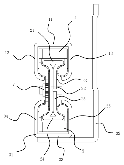
| 1 | Movable rail | Connects to the drawer side plate; has an upper flat plate part (11), left vertical part (12) and right vertical part (13) with inward round corners. |
| 2 | Middle rail | Carries the gear; has an upper flat plate part II (21), left vertical part II (22), upper right vertical part II (23), lower flat plate part II (24) and lower right vertical part II (25) with concave arc transitions. |
| 3 | Fixed rail | Mounts to the cabinet; includes a support end (31) welded to an L-shaped connecting end (32), with a lower flat plate portion III (33), left vertical portion III (34) and right vertical portion III (35) with fillets. |
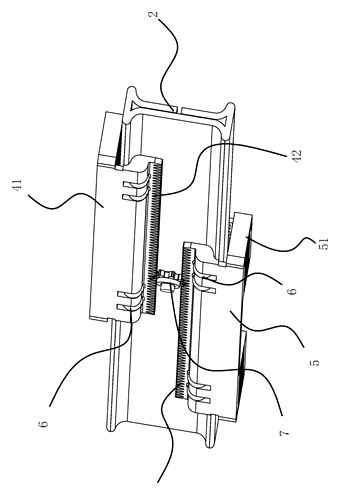
| 4 | Upper retainer | Door-frame shaped body (41) carrying rollers and balls (6); provides the downward-facing upper rack (42). |
| 5 | Lower retainer | Door-frame shaped body (51) carrying rollers and balls (6); provides the upward-facing lower rack (52). |
| 6 | Balls | Arranged in rows on the left and right sides of the retainers to roll against the arc transitions and fillets. |
| 7 | Gear | Rotatably connected to the middle rail; meshes with both racks to drive the middle rail. |
Operating steps
- Pull the drawer. The movable rail (1) begins to extend outward from the cabinet.
- The upper rack engages the gear. As the movable rail moves, the upper rack (42) on the upper retainer (4) turns the gear (7) mounted on the middle rail (2).
- The gear drives the lower rack. The turning gear simultaneously pushes against the lower rack (52) on the lower retainer (5), forcing the middle rail to slide out along the fixed rail (3) in a synchronized ratio.
- Rollers and balls guide the travel. The rollers on the retainers roll between the flat plates of the rails, while the balls (6) roll between the concave arc transitions of the middle rail and the fillets of the outer rails, keeping the assembly aligned.
- Push to close. Pushing the drawer reverses the process; the gear drives the middle rail back into the cabinet alongside the movable rail.
Applications
Kitchen base cabinets
Homeowners open kitchen drawers dozens of times a day, often with heavy pots inside. The gear drive coordinates the rail extension so the drawer does not rack or bind under load, keeping the operation quiet.
Office filing pedestals
File drawers carry dense paper loads and are cycled constantly in workspaces. Standard slides can develop uneven wear from the friction, but the gear and rack transmission distributes the movement evenly across the sections.
Bathroom vanities
Vanity drawers operate in humid environments where moisture can increase friction on metal surfaces. By reducing sliding contact between the rails, the gear mechanism helps maintain consistent travel over time.
Ready-to-assemble furniture
RTA buyers assemble drawers without specialized tools or experience. A slide that extends smoothly without catching makes the assembly process easier and reduces returns caused by perceived hardware defects.
Retail display fixtures
Store staff pull out display drawers repeatedly to show products to customers. The synchronized movement ensures the drawer glides out steadily, presenting merchandise without sudden jolts.
Where it is less suitable
- Heavy industrial tool chests - applications requiring extreme load ratings may need larger ball-bearing systems designed for those specific weights.
- Undermount concealed slides - this patent describes a side-mount configuration where the movable rail connects to the side plate; undermount designs use different geometry.
- Lowest-cost promotional furniture - the addition of a gear, two racks, and machined retainers adds component cost compared to basic single-rack or friction slides.
Frequently asked questions
How does the gear synchronize the drawer rails?
A gear is mounted on the middle rail. It meshes with a downward-facing rack on the upper retainer and an upward-facing rack on the lower retainer. When you pull the movable rail, the gear turns and drives the middle rail along the fixed rail at the same time, coordinating the extension of all three sections.
Why does this design reduce noise?
The patent states that the gear transmission replaces the sliding friction normally found between the middle rail and the fixed rail. Because the movement is driven by the meshing gear teeth rather than surfaces dragging against each other, the friction is reduced, which lowers the noise generated during opening and closing.
What are the retainers made of?
The patent describes the retainers as having a door frame-shaped body that carries rows of rollers and balls. The specific material is not named in the document and is set in design / confirmed on prototypes depending on the load class and cost targets.
How do the balls and rollers work inside the slide?
The rollers run horizontally between the flat top and bottom plates of the adjacent rails to support the vertical load. The balls are arranged on the left and right sides of the retainers and roll vertically between the inwardly concave arc transitions of the middle rail and the fillets of the outer rails, keeping the assembly centered and preventing lateral play.
Is the fixed rail one piece?
According to the patent, the fixed rail consists of two parts: a support end and an L-shaped connecting end. The support end is welded to the connecting end. This differs from some standard slides that use a single continuous roll-formed profile.
What sizes are available?
The patent document does not list specific lengths or load capacities. Dimensions such as overall length, steel thickness, and gear size are set in design / confirmed on prototypes to match the buyer’s cabinet specifications.
Can this design be made and sold in the US?
The patent was filed only in China and has no US or other foreign counterpart. However, it remains in force in China until at most 2029-05-07 (if annual fees are paid), meaning production in China requires the owner’s permission. Additionally, other companies hold later patents citing this design in the gear-synchronized slide field, so a freedom-to-operate review for the US market is recommended before volume production.
Are you affiliated with the patent owner?
No. IP2M is an independent design and manufacturing service working from the public patent document.
Request a quote
Click Request a Quote below to see our email address - copy it, or open your email app with a ready-made message. Please mention patent CN210672684U in the subject.
Helpful details to include:
- Your company and channel (cabinet maker, furniture brand, hardware distributor)
- Target drawer lengths and load requirements
- Preferred finish (zinc plating, powder coat, etc.)
- Mounting hole pattern or cabinet dimensions
- Estimated quantity per order
- Timeline - when you need prototypes and the first production shipment
You can also reach us at (332) 203-9997.
Explore this product
Interested in building this?
Tell us your target market, quantity and timeline. We reply with options for prototyping, small-batch runs or volume production.
Send your inquiry to
Please put CN210672684U in the subject line and tell us your company, country, estimated quantity and timeline.
Prefer to talk? Call (332) 203-9997.
More product-ready patents
All Furniture, Bedding & Storage patents →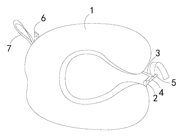
Furniture, Bedding & Storage
Roll-Up Travel Neck Pillow with Buckles
U-shaped travel pillow with a front buckle and a back buckle that holds it rolled up for carrying.
Patent CN206543091U
Furniture, Bedding & Storage
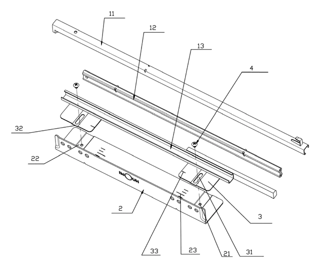
Width-Adjustable Slide Rail for Pull-Out Baskets
Basket slide rail on a slotted, scaled adjusting plate, so one pull-out basket fits several cabinet widths.
Patent CN208909382U
Furniture, Bedding & Storage
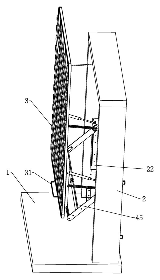
Lift-Up Storage Bed with Four-Bar Linkage That Slides the Deck Away from the Headboard
Storage bed deck that rises on four-bar linkages and gas springs, clearing the headboard as it opens.
Patent CN210870645U
Furniture, Bedding & Storage
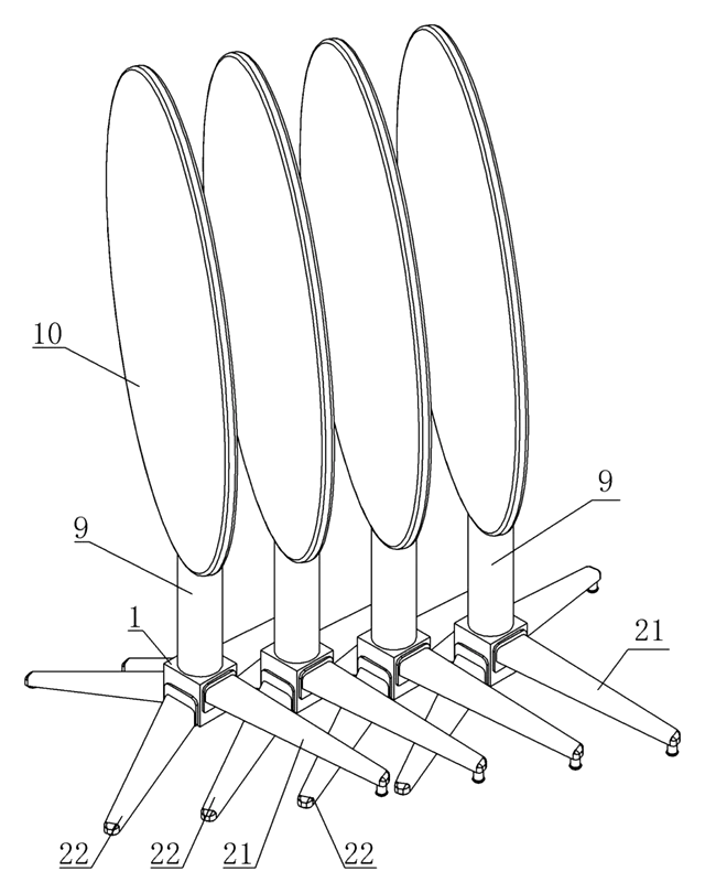
Self-Leveling, Nesting Table Base with a Torsion-Ring Leg Hub
Four-leg base that self-levels through a torsion-ring hub and nests sideways with flip-top tables.
Patent CN211483640U
Furniture, Bedding & Storage
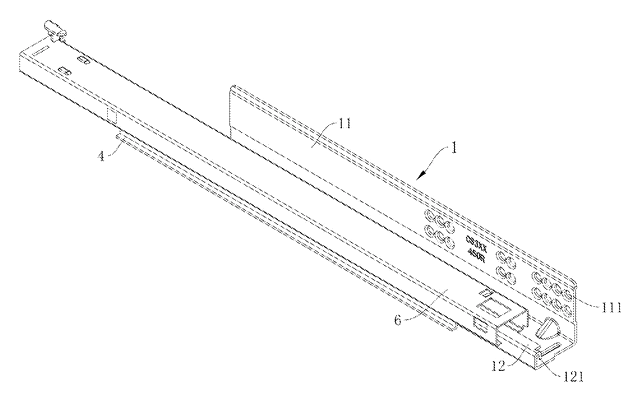
Rack-and-Pinion Synchronized Drawer Slide with a Folded-In Fixed Rail
Full-extension drawer slide: a pinion between two racks keeps the rails moving in step.
Patent CN206314843U
Furniture & Bedding
Dual-Zone Split-Spring Mattress with Removable Fabric Cover
Half-pocket, half-standard spring mattress sharing one base plate, with a removable cover.
Patent CN208355064U
Browse by category
- Apparel & Accessories (22)
- Baby & Kids (16)
- Bags & Luggage (9)
- Bath & Personal Care (16)
- Car Accessories (10)
- Furniture, Bedding & Storage (12)
- Garden & Outdoor (18)
- Health & Wellness (8)
- Home, Kitchen & Cleaning (24)
- Lighting (12)
- Packaging & Containers (6)
- Pet Products (6)
- Phone & Camera Accessories (4)
- Retail Display (13)
- School, Office & Art (19)
- Sports & Recreation (25)
- Tools & Workshop (27)
- Toys & Games (12)
This page is based on the public patent document CN210672684U, assigned to Haining Yicheng Hardware Co ltd. IP2M is an independent manufacturing service and is not affiliated with, endorsed by or licensed by the patent owner. Images marked as concept renderings are illustrations, not photos of an existing product. Patent status information is provided for reference only and is not legal advice; confirm freedom to operate for your market before production. Full disclaimer.