At a glance
| Patent number | CN210672684U (application CN201920646303) |
| Type | China utility model (实用新型) - protects product shape and structure |
| Original title | Three-section drawer sliding rail assembly (一种三节抽屉滑轨组件) |
| Patent owner | Haining Yicheng Hardware Co ltd |
| Inventors | Chu Zhifeng |
| Filing date | 2019-05-07 |
| Grant date | 2020-06-05 |
| Status (China) | In force in China until at most 2029-05-07 (if annual fees are paid) |
| Patent family | Chinese filings only - no US, European, Japanese, PCT or other filings listed |
| Cited by | 5 later documents |
| Source | Google Patents (search for CN210672684U) |
What the claims cover, in plain language
Claim 1 - a three-section drawer slide assembly with a movable rail, a middle rail, and a fixed rail for connection to a cabinet. The movable rail connects to a side plate and is supported on the middle rail. The middle rail has an upper flat plate part II bent downwards at both ends into a left vertical part II and an upper right vertical part II; the left vertical part bends right into a lower flat plate part II, which bends up into a lower right vertical part II. The fixed rail has a support end welded to a connecting end, with a lower flat plate portion III parallel to the movable rail’s upper flat plate, and vertical portions III with inward fillets. An upper retainer between the movable and middle rails has a downward upper rack; a lower retainer between the middle and fixed rails has an upward lower rack. A gear is rotatably connected to the middle rail, and both racks mesh with the gear.
Claim 2 - the junctions between the middle rail’s flat and vertical parts are inwardly concave arc transitions. Claim 3 - the fixed rail’s connecting end is L-shaped in cross-section, and the lower flat plate portion III is welded to it. Claim 4 - the upper retainer has a door frame-shaped body with a row of rollers and rows of balls on the left and right sides. The rollers sit between the upper flat plates of the movable and middle rails; the balls sit between the arc transitions of the vertical parts. Claim 5 - the lower retainer also has a door frame-shaped body with rollers and balls, positioned between the lower flat plates and the fillets/arc transitions of the middle and fixed rails.
This is a simplified reading for orientation only. The legal scope is defined by the exact claim wording in the official Chinese document.
What this means for US production
This patent was filed only in China and is currently in force there (until at most 2029-05-07, provided annual fees are paid). It has no US or other foreign counterpart. However, making or selling this exact design in China needs the owner’s permission while the patent remains active.
Two points to settle early:
- Other patents may exist. Segos Co., Ltd. (주식회사 세고스) holds later Korean and international filings (KR20210153868A, WO2023286888A1) citing this document, and Dongguan Dige Hardware Products Co., Ltd. holds WO2022041560A1 citing it, indicating ongoing patent activity in gear-synchronized drawer slides globally. A freedom-to-operate (FTO) review covering the US market is recommended before tooling.
- Welded fixed rail construction. Claim 3 specifies the support end is welded to the L-shaped connecting end. If your production line uses continuous roll-forming for the entire fixed rail rather than welding two pieces, confirm whether that structural change affects the FTO analysis or requires separate testing.
Customization and manufacturing
What can be customized
| Area | Options |
|---|---|
| Length | To be confirmed in design based on cabinet depth |
| Material thickness | Set in design for the target load class |
| Finish | Zinc plating, powder coating, or other surface treatments |
| Gear and rack pitch | Confirmed on prototypes to balance travel speed and noise |
| Retainer material | Plastic or steel, set in design |
| Mounting holes | Pattern matched to the buyer’s cabinet specifications |
Things to plan for (US market)
- ANSI/BHMA A156.9 - the standard for cabinet hardware, covering cycle life, static load, and dynamic tests for drawer slides.
- Tip-over stability (STURDY Act, 16 CFR 1261) - clothing storage units sold in the US must pass stability testing; full-extension slides affect the center of gravity when the drawer is open.
- California Proposition 65 - surface finishes, plating chemicals, and plastic retainer materials must be screened for listed substances.
How a project runs
- Inquiry - define the required lengths, load capacity, finish, and quantity.
- Design - engineer the rail profiles, gear tooth geometry, rack pitch, and retainer shapes.
- Prototype - produce samples to verify gear meshing, noise levels, and travel smoothness.
- Pilot run - conduct cycle testing, load testing, and corrosion checks on the chosen finish.
- Production - stamp or roll-form the rails, mold or stamp the retainers, machine or mold the gear and racks, weld the fixed rail components, apply finishes, and assemble.
Quantities & timeline
Manufacturing requires stamping dies or roll-forming tooling for each rail profile, injection molds if the retainers or gears are plastic, and welding fixtures for the fixed rail assembly. Cycle testing to validate the gear synchronization takes several weeks of continuous operation. Send us your target lengths, load requirements, finish preferences, estimated quantities and timeline, and we will reply with options.
Patent drawings
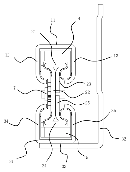
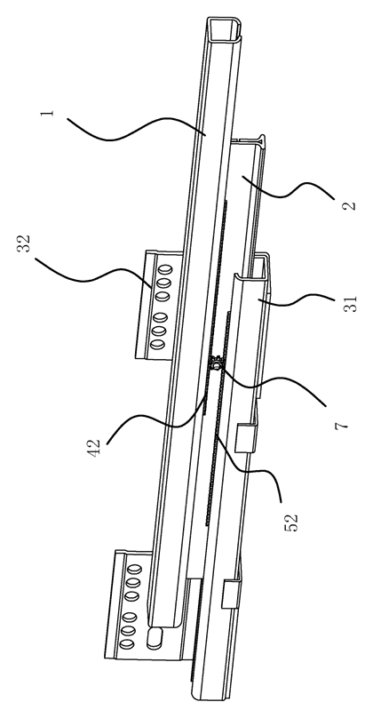
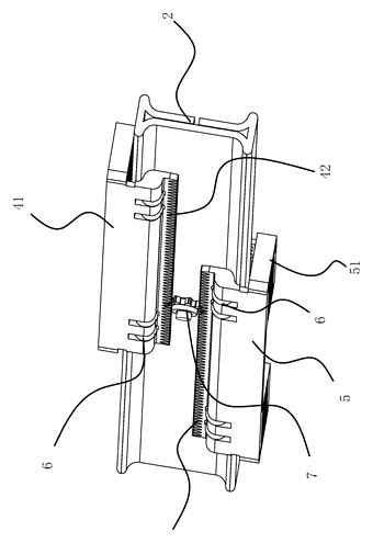
Drawings reproduced from the public patent document for reference.