Patent Information & Production OptionsElectric Flat Mop Cleaning Bucket with Automatic Washing and Wringing · Patent CN212261293U

Patent CN212261293U: bibliographic data, legal status, family, a plain-language reading of the claims, plus customization, US compliance points and how a manufacturing project runs.

At a glance

Patent numberCN212261293U (application CN202020159775)
TypeChina utility model (实用新型) - protects product shape and structure
Original titleFlat mop belt cleaning device (一种平板拖把清洗装置)
Patent ownerBazhou Liangjie Household Products Co Ltd
InventorsYao Guohui, Ren Junshan, Yao Guojie
Filing date2020-02-11
Grant date2021-01-01
Status (China)In force in China until at most 2030-02-11 (if annual fees are paid)
Patent familyChinese filings only - no US, European, Japanese, PCT or other filings listed
Cited by1 later document
SourceGoogle Patents (search for CN212261293U)

What the claims cover, in plain language

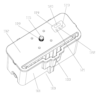
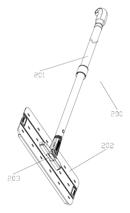
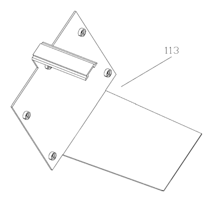
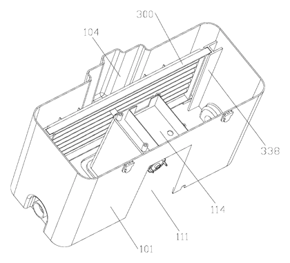
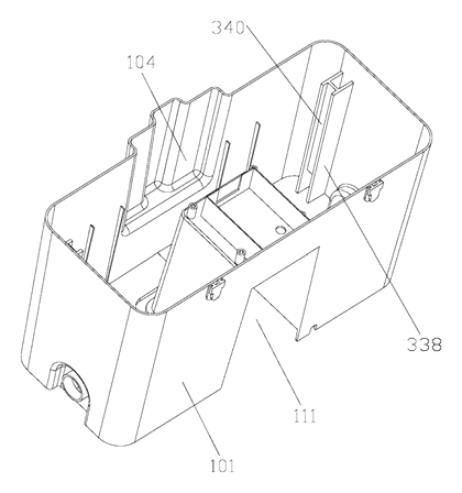
Claim 1 - A flat mop cleaning device comprising a mop bucket and a flat mop. The flat mop includes a mop rod and a mop head movably connected to the rod, with wiping material on the head. The mop bucket includes a bucket body and a bucket cover fixed over the upper opening of the body. An insertion hole is provided on the cover. The flat mop is inserted through this hole so the wiping material is washed inside the bucket body, and then squeezed after washing is complete.

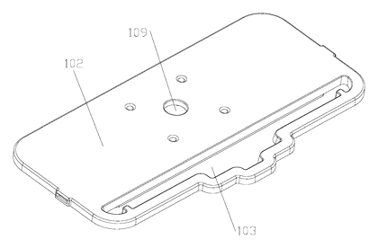
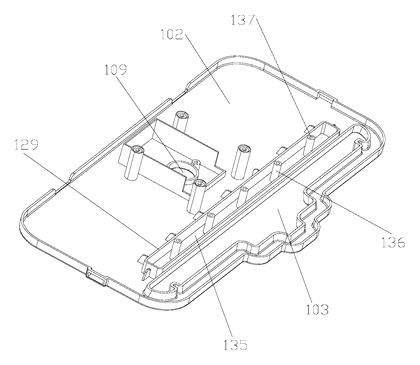
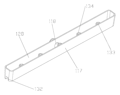
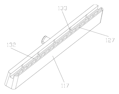
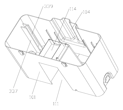
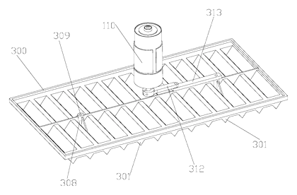
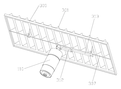
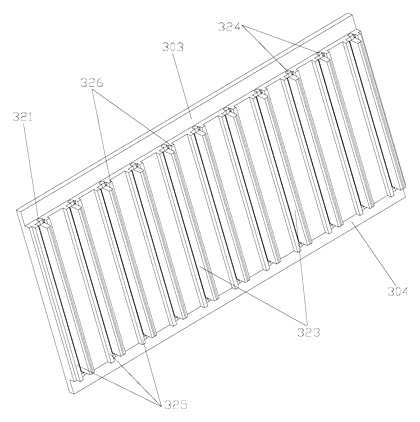
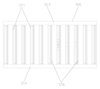
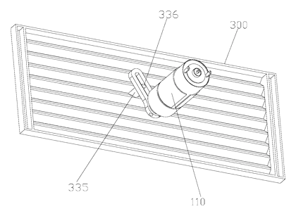
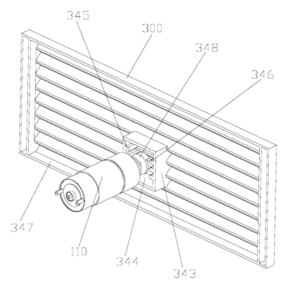
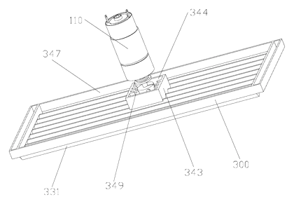
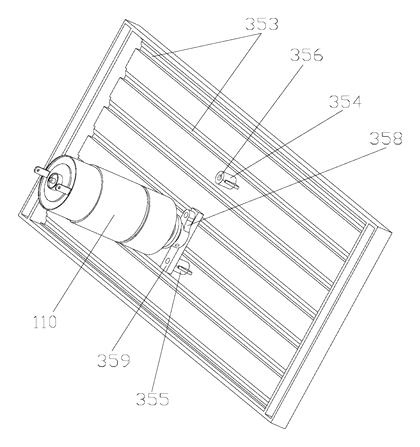
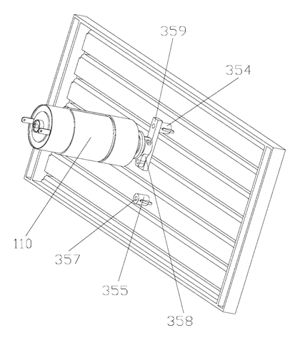
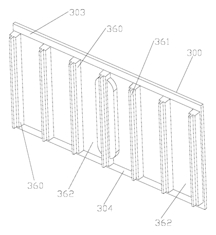
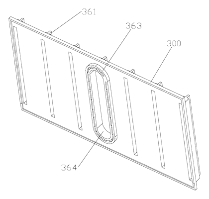
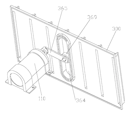
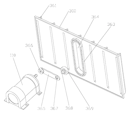
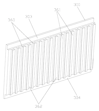
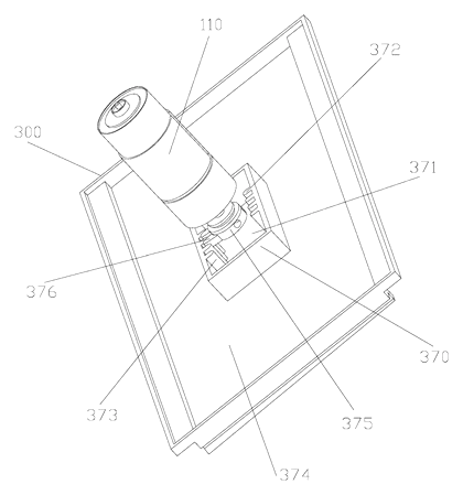
Claim 2 - The inner sidewall of the bucket body has a positioning recess located below and corresponding to the insertion hole. Claim 3 - A positioning boss is fixed on the opposite inner sidewall, protruding inward, working together with the recess to guide the mop. Claim 4 - A cleaning mechanism is disposed inside the bucket body to perform the washing and wringing. Claim 5 - A driving mechanism inside the bucket drives the cleaning mechanism to operate automatically. Claim 6 - A reed switch is placed in the positioning recess, and a magnet is fixed at the lower end of the mop rod. Inserting the mop aligns the magnet with the switch to trigger automatic washing and subsequent squeezing. Claim 7 - A solenoid valve and circuit board are provided. The reed switch and solenoid valve connect to the board. The valve sits in a water inlet channel; triggering the switch opens the valve to let water in for washing, and closing it stops the flow for squeezing. Claims 8-10 onward - Detail the driving motor mounted in an external recess, connected to the cleaning assembly via a connecting assembly passing through the bucket wall.

This is a simplified reading for orientation only. The legal scope is defined by the exact claim wording in the official Chinese document.

What this means for US production

This patent was filed only in China and is currently in force there. It has no US or other foreign counterpart. However, because it is active in China, making or selling this specific design in China needs the owner’s permission. Manufacturing outside of China for sale in the US is not restricted by this particular document.

Two points to settle early:

  • Other patents may exist. Motorized mop buckets and self-wringing cleaning systems are actively patented globally by various appliance manufacturers. Although no foreign patents cite this specific Chinese utility model, competing designs for automated mop washing exist. A freedom-to-operate (FTO) review focusing on the magnetic trigger, solenoid water control, and motor-driven wringing mechanism is necessary before committing to tooling for the US market.
  • Water and electrical separation. The patent places the motor in an external recess and seals the reed switch in a guide tube. For US production, the engineering team must verify that these sealing methods meet consumer safety expectations for devices combining water flow and electrical motors.

Customization and manufacturing

What can be customized

AreaOptions
Bucket dimensionsSized to fit standard flat mop widths (to be confirmed in design)
Power sourceAC adapter for stationary use, or rechargeable battery pack for cordless carts
Water inletThreaded fitting for garden hose, or quick-connect for indoor plumbing
Motor typeBrushed or brushless DC motor, selected based on torque needed for wringing
PlasticsPP or ABS for the bucket body and cover; material grade chosen for impact resistance
Control logicCircuit board programmed for specific wash/wring durations (set in design / confirmed on prototypes)
Mop compatibilityInsertion hole profile adapted to the buyer’s specific flat mop head dimensions

Things to plan for (US market)

  • UL 1017 or UL 499 - Depending on whether the device is classified primarily as a motorized floor-care appliance or a water-heating/pumping appliance, Underwriters Laboratories standards for household electrical products apply.
  • FCC Part 15 - The circuit board controlling the motor and solenoid valve emits radio frequency energy and must comply with FCC rules for unintentional radiators sold in the US.
  • California Proposition 65 - All plastics, wiring insulation, and metal components must be screened for listed chemicals.
  • NSF/ANSI 61 or FDA 21 CFR - If the device is marketed for food-service environments where the water contacts food-prep surfaces indirectly, materials touching the water path may need food-contact clearance.

How a project runs

  1. Inquiry - Define the target mop size, power preference, water source type, and expected volume.
  2. Design - Engineer the bucket mold, select the motor and solenoid valve, design the circuit board, and map the waterproof seals.
  3. Prototype - Produce 3D-printed or soft-tooled samples to test the magnetic trigger alignment, water flow rate, and wringing torque.
  4. Pilot run - Manufacture a small batch using production molds for lifecycle testing, electrical safety verification, and water ingress checks.
  5. Production - Injection molding of the bucket and cover, PCBA assembly, motor installation, final waterproofing, and packaging.

Quantities & timeline

The bucket body and cover require large injection molds. The driving motor, solenoid valve, and circuit board are sourced as electronic sub-assemblies. Certification testing for electrical safety and FCC compliance adds significant time before mass production can begin. Send us your target mop dimensions, power requirements, water inlet preferences, estimated order quantity, and target price, and we will reply with options.

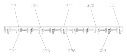
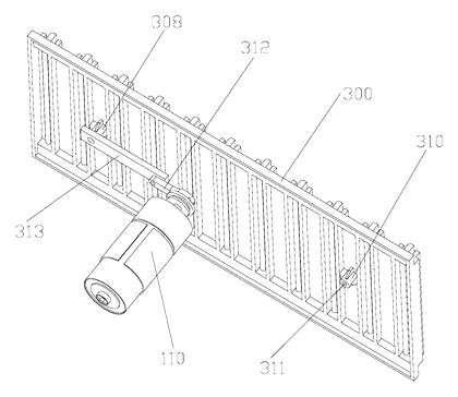
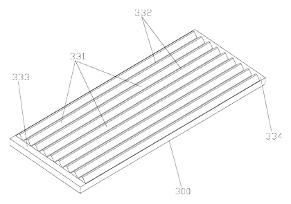
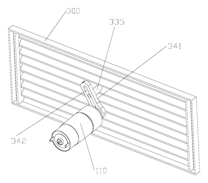
Patent drawings
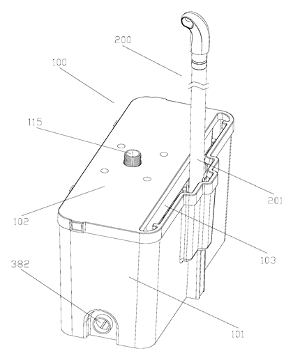
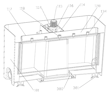
Electric Flat Mop Cleaning Bucket with Automatic Washing and Wringing - Patent Fig. 1
Fig. 1 - Overall view of the flat mop cleaning device.
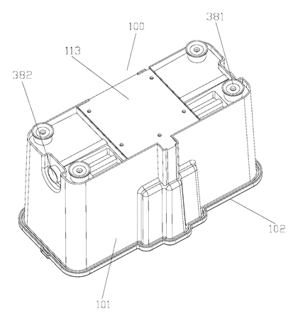
Electric Flat Mop Cleaning Bucket with Automatic Washing and Wringing - Patent Fig. 2
Fig. 2 - View of the bucket body and cover.
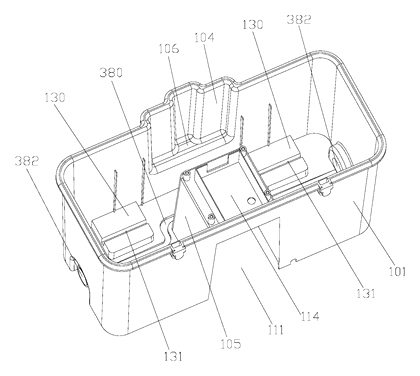
Electric Flat Mop Cleaning Bucket with Automatic Washing and Wringing - Patent Fig. 3
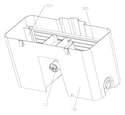
Fig. 3 - Interior structure of the bucket.
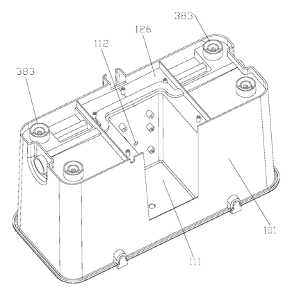
Electric Flat Mop Cleaning Bucket with Automatic Washing and Wringing - Patent Fig. 4
Fig. 4 - Positioning recess and guide tube detail.
Electric Flat Mop Cleaning Bucket with Automatic Washing and Wringing - Patent Fig. 5
Fig. 5 - Positioning boss detail.
Electric Flat Mop Cleaning Bucket with Automatic Washing and Wringing - Patent Fig. 6
Fig. 6 - Driving mechanism layout.
Electric Flat Mop Cleaning Bucket with Automatic Washing and Wringing - Patent Fig. 7
Fig. 7 - Motor mounting recess.
Electric Flat Mop Cleaning Bucket with Automatic Washing and Wringing - Patent Fig. 8
Fig. 8 - Connecting assembly.
Electric Flat Mop Cleaning Bucket with Automatic Washing and Wringing - Patent Fig. 9
Fig. 9 - Solenoid valve position.
Electric Flat Mop Cleaning Bucket with Automatic Washing and Wringing - Patent Fig. 10
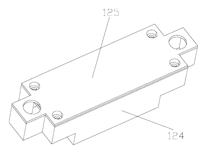
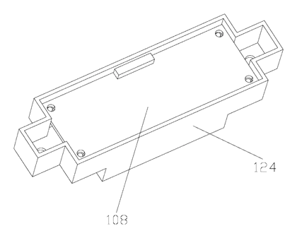
Fig. 10 - Circuit board mounting box.
Electric Flat Mop Cleaning Bucket with Automatic Washing and Wringing - Patent Fig. 11
Fig. 11 - Bottom view of the bucket.
Electric Flat Mop Cleaning Bucket with Automatic Washing and Wringing - Patent Fig. 12
Fig. 12 - Fixing groove detail.
Electric Flat Mop Cleaning Bucket with Automatic Washing and Wringing - Patent Fig. 13
Fig. 13 - Housing and cover of the circuit board box.
Electric Flat Mop Cleaning Bucket with Automatic Washing and Wringing - Patent Fig. 14
Fig. 14 - Magnet on the mop rod.
Electric Flat Mop Cleaning Bucket with Automatic Washing and Wringing - Patent Fig. 15
Fig. 15 - Mop insertion alignment.
Electric Flat Mop Cleaning Bucket with Automatic Washing and Wringing - Patent Fig. 16
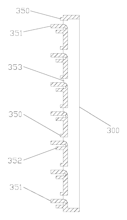
Fig. 16 - Cross-section of the bucket.
Electric Flat Mop Cleaning Bucket with Automatic Washing and Wringing - Patent Fig. 17
Fig. 17 - Water inlet channel.
Electric Flat Mop Cleaning Bucket with Automatic Washing and Wringing - Patent Fig. 18
Fig. 18 - Reed switch placement.
Electric Flat Mop Cleaning Bucket with Automatic Washing and Wringing - Patent Fig. 19
Fig. 19 - Cleaning mechanism view.
Electric Flat Mop Cleaning Bucket with Automatic Washing and Wringing - Patent Fig. 20
Fig. 20 - Wringing action detail.
Electric Flat Mop Cleaning Bucket with Automatic Washing and Wringing - Patent Fig. 21
Fig. 21 - Exploded view of components.
Electric Flat Mop Cleaning Bucket with Automatic Washing and Wringing - Patent Fig. 22
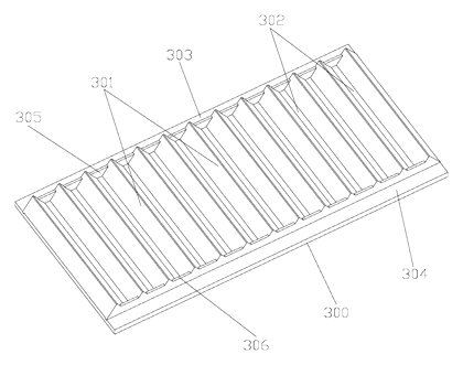
Fig. 22 - Bucket cover underside.
Electric Flat Mop Cleaning Bucket with Automatic Washing and Wringing - Patent Fig. 23
Fig. 23 - Insertion hole geometry.
Electric Flat Mop Cleaning Bucket with Automatic Washing and Wringing - Patent Fig. 24
Fig. 24 - Mop head hinge.
Electric Flat Mop Cleaning Bucket with Automatic Washing and Wringing - Patent Fig. 25
Fig. 25 - Wiping material attachment.
Electric Flat Mop Cleaning Bucket with Automatic Washing and Wringing - Patent Fig. 26
Fig. 26 - Guide tube seal.
Electric Flat Mop Cleaning Bucket with Automatic Washing and Wringing - Patent Fig. 27
Fig. 27 - Motor shaft connection.
Electric Flat Mop Cleaning Bucket with Automatic Washing and Wringing - Patent Fig. 28
Fig. 28 - Valve wiring route.
Electric Flat Mop Cleaning Bucket with Automatic Washing and Wringing - Patent Fig. 29
Fig. 29 - Board box fastening.
Electric Flat Mop Cleaning Bucket with Automatic Washing and Wringing - Patent Fig. 30
Fig. 30 - Bucket wall thickness.
Electric Flat Mop Cleaning Bucket with Automatic Washing and Wringing - Patent Fig. 31
Fig. 31 - Recess and boss alignment.
Electric Flat Mop Cleaning Bucket with Automatic Washing and Wringing - Patent Fig. 32
Fig. 32 - Magnet field reach.
Electric Flat Mop Cleaning Bucket with Automatic Washing and Wringing - Patent Fig. 33
Fig. 33 - Water flow path.
Electric Flat Mop Cleaning Bucket with Automatic Washing and Wringing - Patent Fig. 34
Fig. 34 - Drainage detail.
Electric Flat Mop Cleaning Bucket with Automatic Washing and Wringing - Patent Fig. 35
Fig. 35 - Squeezing roller or plate.
Electric Flat Mop Cleaning Bucket with Automatic Washing and Wringing - Patent Fig. 36
Fig. 36 - Assembly sequence.
Electric Flat Mop Cleaning Bucket with Automatic Washing and Wringing - Patent Fig. 37
Fig. 37 - Cover locking feature.
Electric Flat Mop Cleaning Bucket with Automatic Washing and Wringing - Patent Fig. 38
Fig. 38 - Handle grip area.
Electric Flat Mop Cleaning Bucket with Automatic Washing and Wringing - Patent Fig. 39
Fig. 39 - External water hose fitting.
Electric Flat Mop Cleaning Bucket with Automatic Washing and Wringing - Patent Fig. 40
Fig. 40 - Electrical schematic block.
Electric Flat Mop Cleaning Bucket with Automatic Washing and Wringing - Patent Fig. 41
Fig. 41 - Operational state diagram.
Electric Flat Mop Cleaning Bucket with Automatic Washing and Wringing - Patent Fig. 42
Fig. 42 - Alternative embodiment view.

Drawings reproduced from the public patent document for reference.
🔥 Popularity – views

Bring this product to market

  1. ✓ Patent vetted China-only family and legal status checked
  2. 2 Product brief · now How it works, uses and options written up
  3. 3 Prototype First samples for buyers to review
  4. 4 Pilot run Small first batch for launch customers
  5. 5 Volume production Repeat orders at scale

Buyer interest

– of 100 buyers needed to start prototyping

or request a quote Share to speed it up:

One click, no sign-up. Each vote is one real visitor, and products with the most interest go to prototyping first.

Build team: no members yet. Need a partner, co-funding or skills to build this? Join and we introduce the team once it forms.

Join the build team

Want to develop this product with others? Tell us what you can bring. When the team has enough people, we introduce the members to each other by email.

I can help with (pick any)

Letters only. The team list on this page shows your country and the first 5 letters of your name (e.g. "Micha**"); leave the name blank to appear as "Anonymous".

No money is collected on this site. IP2M does not hold or manage funds, and pledges are non-binding. We email you a link to confirm; only confirmed members are introduced to each other. See our privacy policy.

Interested in building this?

Tell us your target market, quantity and timeline. We reply with options for prototyping, small-batch runs or volume production.

This page is based on the public patent document CN212261293U, assigned to Bazhou Liangjie Household Products Co Ltd. IP2M is an independent manufacturing service and is not affiliated with, endorsed by or licensed by the patent owner. Images marked as concept renderings are illustrations, not photos of an existing product. Patent status information is provided for reference only and is not legal advice; confirm freedom to operate for your market before production. Full disclaimer.