At a glance
| Patent number | CN214637502U (application CN202120020693) |
| Type | China utility model (实用新型) - protects product shape and structure |
| Original title | Rotary self-locking type push spout lid and spray bottle (旋转自锁型按压喷盖及喷雾瓶) |
| Patent owner | Zhongshan Huiyu Packaging Technology Co ltd |
| Inventors | Li Qiuping |
| Filing date | 2021-01-04 |
| Grant date | 2021-11-09 |
| Status (China) | In force - valid until at most 2031-01-04, provided annual maintenance fees are paid |
| Patent family | Chinese filings only - no US, European, Japanese, PCT or other filings listed |
| Cited by | 2 later documents |
| Source | Google Patents (search for CN214637502U) |
What the claims cover, in plain language
Claim 1 defines a rotary self-locking push spout lid comprising a fixed base (1), a pressing nozzle (2) on the base, a rotating cap (3) covering the nozzle, and a press button (4) on the cap. The cap rotates between a latched position and an unblock position. A pressure limiting mechanism restricts the button from descending when the cap is in the latched position, but allows it when in the unblock position.
Claim 2 specifies the limiting mechanism as a limiting plate (11) on the fixed base and a limiting tongue (41) on the button, where the plate blocks the tongue in the locked state. Claim 3 adds a stop gear to limit rotation, consisting of a sliding groove (13) and a sliding hook (31). Claim 4 details the sliding hook’s movement from one end of the groove to the other during unlocking. Claim 5 introduces a screen protrusion (14) and a flexible plectrum (32) to provide tactile and auditory feedback (“click”) when rotating. Claim 6 describes the nozzle structure: a flexible plate (21), nozzle (22), and connecting pipe (23). Claim 7 notes a spray hole (33) in the cap that aligns with the nozzle when unlocked. Claim 8 adds a hole blocking plate (15) to seal the spray hole when locked. Claim 9 describes a clamping mechanism using protruding edges (12) and hooks (31) to attach the cap to the base. Claim 10 claims a spray bottle incorporating the cap defined in claims 1-9.
This is a simplified reading for orientation only. The legal scope is defined by the exact claim wording in the official Chinese document.
What this means for US production
This patent was filed only in China and is currently in force. It does not automatically restrict manufacturing or sales in the United States, as there is no corresponding US patent family member. However, making or selling this specific design in China would require permission from the patent owner.
Two points to settle early:
- Other patents may exist. Spray closures are a highly competitive field with numerous existing US patents covering various locking mechanisms, child-resistant features, and nozzle designs. A freedom-to-operate (FTO) review is essential to ensure your specific implementation of the rotary lock and button interface does not infringe on other active intellectual property in the target market.
- Material Compatibility. The patent describes structural interactions but not specific materials. Resins must be selected based on the chemical compatibility of the liquid inside (e.g., alcohol, bleach, oils) to prevent stress cracking or degradation of the locking tongues.
Customization and manufacturing
What can be customized
| Area | Options |
|---|---|
| Color | Full Pantone matching for cap, base, and button. |
| Finish | Glossy, matte, soft-touch coating, or metallic plating. |
| Nozzle Type | Fine mist, stream, or foaming attachment (requires mold changes). |
| Spring Force | Adjusted via wall thickness of the flexible plate (21) for lighter/heavier press feel. |
| Labeling | Pad printing or laser marking for brand logos on the rotating cap. |
| Dip Tube | Length and diameter customized to bottle size and viscosity. |
Things to plan for (US market)
- CPSC Child-Resistant Packaging (CRP): If the product contains hazardous substances (as defined by 16 CFR 1700), the closure must meet specific opening force and complexity standards. Note that this patent’s design is a lock, not necessarily a certified child-resistant mechanism unless tested and modified accordingly.
- FDA 21 CFR 177: For food-contact applications, all resins and additives must comply with FDA regulations for indirect food additives.
- EPA Registration: If marketed as a pesticide (e.g., certain disinfectants), packaging requirements may involve specific labeling and closure integrity tests.
- Proposition 65: California warnings may be required if the plasticizers or colorants contain listed chemicals.
How a project runs
- Inquiry - Define bottle neck finish, liquid type, and volume requirements.
- Design - CAD modeling of the cap, base, and nozzle to match the patent’s structural logic or adapt it.
- Prototype - CNC machined samples or 3D printed units to test the locking torque and button travel.
- Tooling - Steel molds created for injection molding the cap, base, and button components.
- Production - Injection molding, spring/nozzle assembly, quality control, and packing.
Quantities & timeline
Injection molds for multi-part assemblies like this typically require 4-6 weeks for fabrication. Assembly is largely automated or semi-manual depending on the dip tube insertion method. Initial MOQs are usually set by cavity count and resin minimums. Send us your target volume, bottle specifications, and desired features and we will reply with options.
Patent drawings
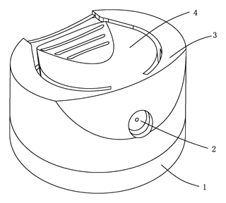
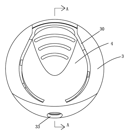
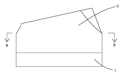
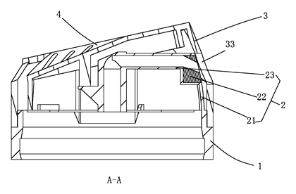
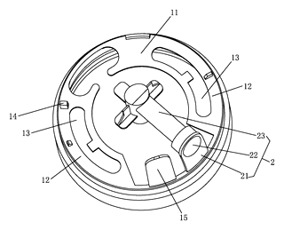
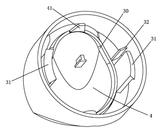
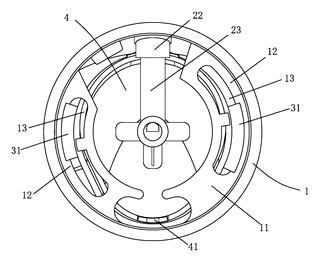
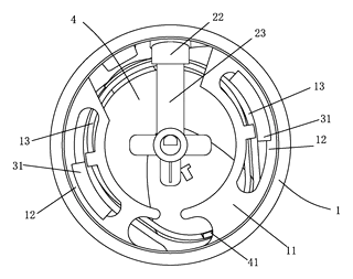
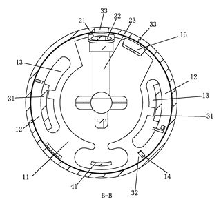
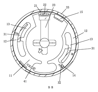
Drawings reproduced from the public patent document for reference.
Production notes
Tooling and process
The primary manufacturing process is injection molding for the fixed base, rotating cap, and press button. Each component requires its own mold cavity. The nozzle assembly may involve ultrasonic welding or snap-fit integration of the flexible plate and pipe. Blow molding is not applicable here as these are rigid structural parts.
Cost drivers
Key cost factors typically include the number of molds and cavities (multi-cavity tools reduce per-unit cost but increase upfront investment) and material grade. High-grade PP or PE resins are needed for durability and chemical resistance. Decoration such as pad printing adds secondary processing costs.
Prototyping path
Initial validation typically starts with a 3D-printed or CNC sample to check the fit of the sliding hook and limiting plate. Once dimensions are confirmed, a tooling phase begins. Testing focuses on drop and leak test protocols to ensure the lock holds under impact and the nozzle seals correctly.
What we would change before tooling
Before finalizing steel molds, we would verify the sealing surface and gasket compression to prevent leaks. We would also adjust the hinge boss or pivot wear areas if the rotation feels too stiff or loose in prototypes. Ensuring the food-contact compliance of the resin is critical if the target market includes consumables.
Common failure points
Potential issues include uneven wall thickness leading to warping of the cap, which disrupts the alignment of the limiting plate. Cracking after drops can occur at stress concentrations near the sliding hook. Stress whitening at corners may appear if the material is too brittle. Finally, misalignment of the shaft and bearing equivalents (the sliding groove/hook interface) can cause the lock to fail to engage.