
Patent CN214968684U
Updated October 28, 2026Switchable Rotation Device for Handheld Massagers
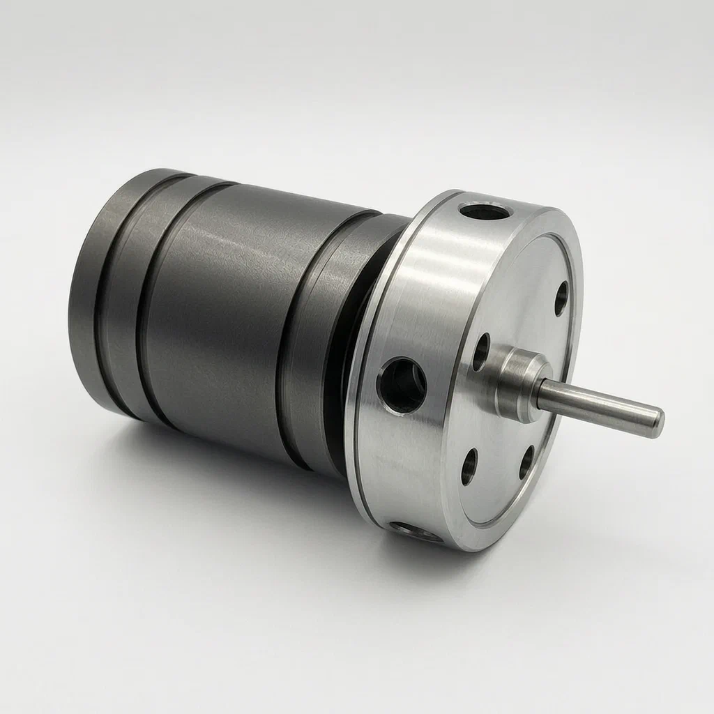
Many massage attachments are either permanently fixed or always free-spinning. This rotating device uses an internal switching push rod to change between those states. When the push rod is moved, its outer profile pushes ball-shaped rotation stoppers outward into matching grooves inside the sleeve member, locking the head at a chosen angle. Moving the push rod back lets the stoppers retract, so the sleeve spins freely on a rolling inner wall. A return spring holds the rod in position until the user switches it again.
- China utility model - in force
- No filings outside China
- Massage & wellness hardware
- Internal push-rod switching mechanism
Splat! What let you down?
🔄
Switchable rotation
An internal push rod moves axially or rotates to lock the sleeve in place or let it spin freely.
⚙️
Ball-type stoppers
Rotation stoppers sit in radial holes and engage circumferential grooves inside the sleeve to hold position.
🔩
Spring-loaded reset
A push rod return spring sits between a buffer abutting part and the rod to maintain the selected state.
📐
Travel limiter
An axial displacement limiting piece controls how far the switching push rod can travel.
Bring this product to market
- ✓ Patent vetted China-only family and legal status checked
- 2 Product brief · now How it works, uses and options written up
- 3 Prototype First samples for buyers to review
- 4 Pilot run Small first batch for launch customers
- 5 Volume production Repeat orders at scale
Buyer interest
– of 100 buyers needed to start prototyping
One click, no sign-up. Each vote is one real visitor, and products with the most interest go to prototyping first.
Build team: no members yet. Need a partner, co-funding or skills to build this? Join and we introduce the team once it forms.
The problem
Standard handheld massagers often come with attachments that are either rigidly fixed to the drive shaft or permanently free-spinning. A fixed head delivers direct percussion but cannot contour to angled muscle groups without forcing the user’s wrist into awkward positions. A permanently spinning head adapts to body curves but lacks stability when targeted pressure is needed on a specific spot. Changing between these two behaviors usually requires swapping out the entire attachment head, which interrupts the session and adds extra parts to carry and store.
The solution
According to the patent, the rotating device is built directly into the attachment interface of a handheld massager. It allows the user to switch the socket member between a locked position and a free-rotating position without detaching the head.
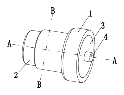
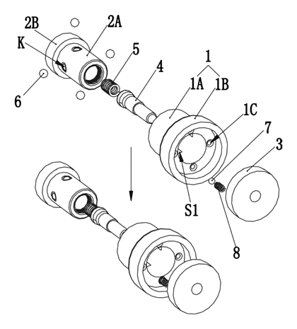
- A sleeve member (1) forms the outer housing of the attachment interface. Its inner wall contains multiple rotation stopper fitting grooves (S1) spaced around the circumference, separated by a smooth inner wall (S2) that allows rolling contact.
- A mounting member (2) fits inside the sleeve. It features a push rod sleeving part (2A) with several radial rotation stopper configuration holes (K).
- Rotation stoppers (6), shaped as balls in this embodiment, sit inside the holes (K). They move radially inward and outward.
- A switching push rod (4) runs through the center of the mounting member. Its outer surface has a thicker rotation-restricting engagement portion (4A) and a narrower rotation-permitting engagement portion (4B).
- When the push rod (4) moves, the thicker portion (4A) pushes the stoppers (6) outward into the grooves (S1), locking the sleeve against rotation. Shifting the rod so the narrower portion (4B) aligns with the stoppers allows them to retract, letting the sleeve spin freely on the inner wall (S2).
- An axial displacement limiting piece (3) and a push rod return spring (5) control the travel and hold the rod in the selected position.
Who it is for
- Handheld massager brands looking to offer an attachment that provides both fixed percussion and free-spinning contouring from a single unit.
- Amazon private-label sellers in the personal care space who need a distinct mechanical feature to differentiate their massage gun listings from basic models.
- Wellness and fitness-recovery wholesalers whose customers want one attachment with both a fixed mode and a free-rolling mode instead of two separate heads.
- OEM factories manufacturing personal care electronics seeking a patented mechanical switching structure to integrate into their existing motor housings.
How it works
The main parts
| No. | Part | What it does |
|---|---|---|
| 1 | Sleeve member | Outer component with grooves (S1) and rolling inner wall (S2); connects to the massage head. |
| 1A | Rotation stopper nesting portion | Inner section of the sleeve containing the grooves. |
| 1B | Restricting piece nesting portion | Wider section of the sleeve that houses the displacement limiter. |
| 1D | Restricting wall | Formed on the outer wall to prevent the stoppers from falling out. |
| 2 | Mounting member | Central body holding the push rod and stoppers; may be a copper sleeve. |
| 2A | Push rod sleeving part | Contains the radial holes (K) for the rotation stoppers. |
| 2B | Buffer abutting part | Wider flange that anchors one end of the return spring. |
| 3 | Axial displacement limiting piece | Sleeved on the push rod to restrict its travel range. |
| 4 | Switching push rod | Moves axially or rotates to switch between locking and freeing the sleeve. |
| 4A | Rotation-restricting engagement portion | Thicker section of the rod that forces stoppers outward. |
| 4B | Rotation-permitting engagement portion | Narrower section that allows stoppers to retract. |
| 4C | Axial movement amount limiting portion | Section of the rod where the limiter (3) is attached. |
| 5 | Push rod return spring | Sits between the buffer part (2B) and the rod to maintain position. |
| 6 | Rotation stopper | Ball-shaped pieces that engage the grooves to lock rotation. |
| 7 | Embedded part | Pushed into a positioning recess by the spring part (8) to hold the selected position. |
| 8 | Spring part | Sits in the mounting member between the embedded part (7) and the bottom wall. |
Operating steps
- To lock the attachment: The user actuates the switching push rod (4) along its axis or rotates it. The rotation-restricting engagement portion (4A) aligns with the rotation stoppers (6).
- The radial dimension of portion (4A) pushes the ball-shaped stoppers (6) outward through the holes (K) until they seat into the rotation stopper fitting grooves (S1) inside the sleeve member (1).
- The sleeve member (1) is now locked to the mounting member (2) and cannot rotate. The push rod return spring (5) holds the rod in this position.
- To allow free rotation: The user shifts the push rod (4) back. The narrower rotation-permitting engagement portion (4B) aligns with the stoppers (6).
- The stoppers (6) retract radially inward, clearing the grooves (S1). The sleeve member (1) now rolls freely on the inner wall (S2) between the grooves.
- The restricting wall (1D) ensures the stoppers (6) do not fall out of the holes (K) when retracted.
Applications
Fixed-head mode
Some users want the attachment to stay rigid on one spot. By shifting the push rod to the restricting position, the stoppers engage the grooves, locking the head firmly in line with the drive shaft so no energy is lost to unwanted spinning.
Contouring over joints
When working around curved areas like shoulders or knees, a rigid head can slip off target. Switching the rod to the permitting position retracts the stoppers, allowing the sleeve to roll freely on its inner wall so the attachment follows the body’s shape smoothly.
Switching modes in one session
Users moving between fixed and rolling use currently have to swap attachments mid-session. This mechanism allows them to transition from fixed percussion to adaptive rolling with a single push or twist of the rod, keeping the workflow uninterrupted.
Portable travel kits
Consumers packing light for travel want fewer accessories to carry. A single attachment head that offers both locked and spinning modes replaces two separate heads, reducing the bulk of the carrying case.
Where it is less suitable
- Fully sealed waterproof massagers - the sliding or rotating push rod creates internal gaps that complicate full submersion sealing.
- Ultra-mini pocket massagers - the nested sleeve, mounting member, and push rod require a minimum diameter that may exceed the size limits of micro-scale devices.
- Direct-drive percussive units without rotational needs - if the product only ever requires rigid impact, the added components for switching rotation are unnecessary.
Frequently asked questions
How does the attachment switch between spinning and locked?
Inside the device, a central push rod has a thick section and a narrow section. When the thick section aligns with the internal ball stoppers, it pushes them outward into grooves in the outer sleeve, locking it. When shifted so the narrow section aligns, the balls retract, and the sleeve spins freely.
Can the user switch it with one hand?
The patent covers two methods: pushing the rod along its axis or twisting it around its circumference. Both actions can be designed as a thumb button or a twist ring on the outside of the massager head for one-handed operation.
What are the rotation stoppers made of?
The patent specifies that in one embodiment, the rotation stoppers are balls. Another embodiment mentions balls made of a rubber material, which deform slightly to fit into the configuration holes during assembly. Metal balls are also implied by the rolling fit description.
How many locking positions are there?
The patent describes an embodiment with four rotation stopper fitting grooves spaced evenly along the circumference. The exact number of grooves and stoppers is set in design and confirmed on prototypes depending on the required angular resolution.
Does the free-spinning mode have friction?
When unlocked, the stoppers retract from the grooves, and the sleeve member rolls on a smooth inner wall located between the grooves. This provides a rolling fit rather than a sliding friction surface.
Is this mechanism compatible with all massage heads?
The rotating device acts as the interface between the massager’s drive shaft and the attachment head. The outer dimensions and connection style of the sleeve member are set in design to match specific foam, plastic, or silicone heads.
Can this design be made and sold in the US?
This patent was filed only in China and is currently in force there. There is no US or other foreign counterpart, so this specific document does not restrict making or selling the design in the United States. However, handheld massager attachments are a crowded patent space - see Patent & Production - so we recommend a freedom-to-operate check before volume production.
Are you affiliated with the patent owner?
No. IP2M is an independent design and manufacturing service working from the public patent document.
Request a quote
Click Request a Quote below to see our email address - copy it, or open your email app with a ready-made message. Please mention patent CN214968684U in the subject.
Helpful details to include:
- Your company and channel (massager brand, Amazon seller, wellness wholesaler, OEM factory)
- Actuation preference (axial push or circumferential twist)
- Target dimensions for the attachment interface
- Material preferences for the sleeve, stoppers, and mounting member
- Estimated quantity and target price
- Timeline - when you would like prototypes and the first shipment
You can also reach us at (332) 203-9997.
Explore this product
Interested in building this?
Tell us your target market, quantity and timeline. We reply with options for prototyping, small-batch runs or volume production.
Send your inquiry to
Please put CN214968684U in the subject line and tell us your company, country, estimated quantity and timeline.
Prefer to talk? Call (332) 203-9997.
More product-ready patents
All Health & Wellness patents →
Health & Wellness
Wrist-Mounted Umbrella Stabilizer
Wrist-worn umbrella holder with an anti-shake link; the patent designs it for people with tremor.
Patent CN212545964U
Health & Wellness
Spring-Valve Breath Trainer for Singers
Pocket breath trainer: blow against a spring-loaded valve to practice breath support for singing.
Patent CN207833725U
Health & Wellness
Closed-Loop Nasal Rinse Kit with Collection Bottle
Nasal rinse set: syringe-fed nose plug inside a sealed hood, with used solution drawn into a bottle.
Patent CN208017763U
Health & Wellness
Inflatable Cervical Traction Collar Shaped for a Child's Neck
Child-size three-ring air collar on telescoping shoulder struts, inflated with a hand bulb.
Patent CN208958444U
Massage & Wellness
Pneumatic Multi-Directional Neck Traction Collar
Three-airbag cervical collar that inflates in sequence to guide the head in multiple directions.
Patent CN207202980U
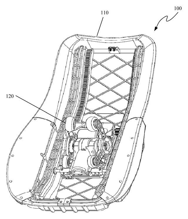
Health & Wellness
Shoulder-Detecting Massage Chair Mechanism with Forked Swing Arms
Massage chair core uses forked swing arms and sensors to detect shoulders and adjust the routine.
Patent CN106618998B
Browse by category
- Apparel & Accessories (22)
- Baby & Kids (16)
- Bags & Luggage (9)
- Bath & Personal Care (16)
- Car Accessories (10)
- Furniture, Bedding & Storage (12)
- Garden & Outdoor (18)
- Health & Wellness (8)
- Home, Kitchen & Cleaning (24)
- Lighting (12)
- Packaging & Containers (6)
- Pet Products (6)
- Phone & Camera Accessories (4)
- Retail Display (13)
- School, Office & Art (19)
- Sports & Recreation (25)
- Tools & Workshop (27)
- Toys & Games (12)
This page is based on the public patent document CN214968684U, assigned to Xiamen Xinzhaochen Electronic Co ltd. IP2M is an independent manufacturing service and is not affiliated with, endorsed by or licensed by the patent owner. Images marked as concept renderings are illustrations, not photos of an existing product. Patent status information is provided for reference only and is not legal advice; confirm freedom to operate for your market before production. Full disclaimer.