At a glance
| Patent number | CN214968684U (application CN202022726904) |
| Type | China utility model (实用新型) - protects product shape and structure |
| Original title | Rotating device and handheld massager (一种旋转装置和手持式按摩器) |
| Patent owner | Xiamen Xinzhaochen Electronic Co ltd |
| Inventors | Hong Zhongjin, Chen Zongling |
| Filing date | 2020-11-23 |
| Grant date | 2021-12-03 |
| Status (China) | In force in China until at most 2030-11-23 (if annual fees are paid) |
| Patent family | Chinese filings only - no US, European, Japanese, PCT or other filings listed |
| Cited by | 2 later documents |
| Source | Google Patents (search for CN214968684U) |
What the claims cover, in plain language
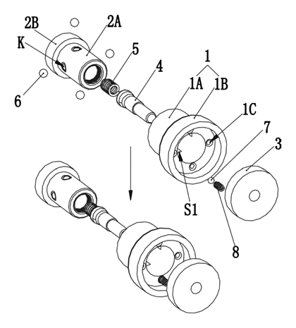
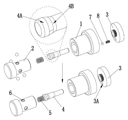
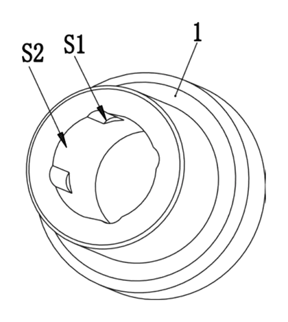
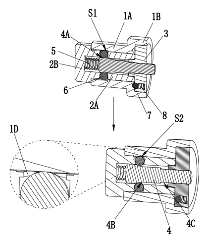
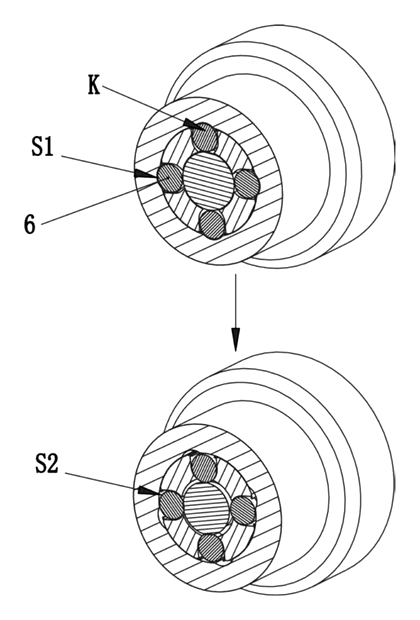
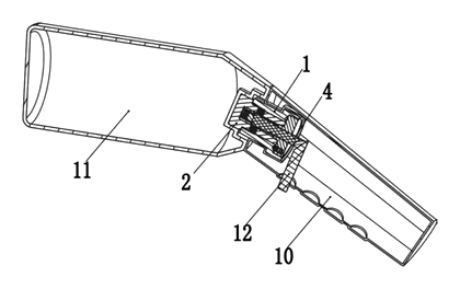
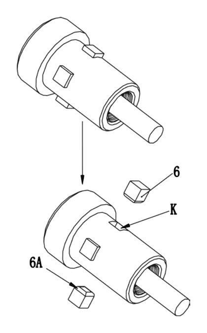
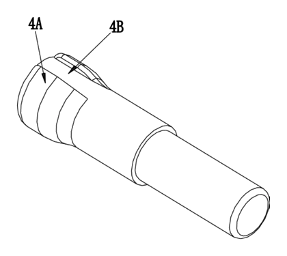
Claim 1 - a rotary device with a mounting piece (2) having a push rod sleeving part (2A) containing a rotation stopping piece configuration hole (K). A rotation stopper (6) sits in the hole (K) and moves radially between a restricting position and a permitting position. A sleeving piece (1) has a rotating stopping piece sleeving part (1A) that fits over the push rod sleeving part (2A). The inner wall of (1A) has multiple rotating stopping piece matching grooves (S1) spaced around the circumference. A switching push rod (4) has a rotation-restricting engagement portion (4A) and a rotation-permitting engagement portion (4B) on its outer edge. Portion (4A) is thick enough to hold the stopper (6) in the restricting position, while portion (4B) is narrow enough to let it move inward to the permitting position. These two portions sit next to each other axially or circumferentially, so moving or turning the push rod (4) switches the state.
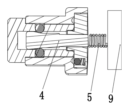
Claim 2 - the restricting (4A) and permitting (4B) portions are adjacent axially; a buffer abutting part (2B) and a push rod reset spring (5) are placed between the buffer part and the push rod. Claim 3 - the restricting portion (4A) sits axially between the spring (5) and the permitting portion (4B). Claim 4 - an axial displacement amount limiting member (3) is placed on the side of the push rod away from the spring to limit travel. Claim 5 - the push rod has an axial movement amount limiting portion (4C); the permitting portion (4B) is between the restricting portion (4A) and the limiting portion (4C), and the limiting member (3) sleeves over (4C). Claim 6 - the limiting member (3) is fixed to the push rod socket portion (2A). Claim 7 onward - details regarding positioning holes (1C) arranged circumferentially on the nesting portion.
This is a simplified reading for orientation only. The legal scope is defined by the exact claim wording in the official Chinese document.
What this means for US production
This patent was filed only in China and is currently in force. Making or selling this exact rotating device structure in China needs the owner’s permission. Because there is no US counterpart, the design itself is not restricted by this specific patent in the United States.
Two points to settle early:
- Other patents may exist. The handheld massager and attachment interface field is heavily patented globally. While no foreign patents cite this specific Chinese document, major personal care brands hold numerous US patents covering attachment locking mechanisms, quick-release interfaces, and percussive motor assemblies. A freedom-to-operate (FTO) review of your final attachment interface is necessary before tooling.
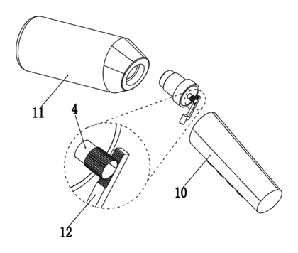
- Actuation method. The patent covers both axial pushing and circumferential twisting of the rod. You must decide which user action fits your massager’s exterior shell, as this dictates the external button or collar design.
Customization and manufacturing
What can be customized
| Area | Options |
|---|---|
| Stopper count | Number of balls and grooves to be confirmed in design (the example shows 4) |
| Actuation style | Axial push-button or circumferential twist-ring |
| Materials | Mounting member can be a copper sleeve or other alloys; stoppers can be metal or rubber balls |
| Outer dimensions | Diameter and length set in design to match the host massager’s shaft |
| Spring tension | Return spring stiffness adjusted for the desired click feel |
| Head compatibility | Interface shape adapted to accept various foam or hard massage tips |
Things to plan for (US market)
- FDA 21 CFR - if the massager is marketed with claims that affect the structure or function of the body beyond general relaxation, it may be regulated as a medical device. General wellness products follow different labeling rules.
- FCC Part 15 - the host handheld massager contains a motor and electronic controls that must meet electromagnetic interference standards.
- UL / ETL listing - lithium-ion battery-powered massagers sold through major US retailers typically require safety certification for the battery pack and charging circuit.
- California Prop 65 - materials used for the sleeve, stoppers, and outer grips must be screened for listed chemicals.
How a project runs
- Inquiry - define the actuation method, dimensions, and host massager specifications.
- Design - engineer the push rod profiles, groove spacing, and spring rates based on the required torque load.
- Prototype - machine samples to test the switching action, rolling friction, and locking strength.
- Pilot run - assemble pilot units into the final massager housing for endurance and vibration testing.
- Production - manufacture the sleeve and mounting members, mold or machine the push rods, assemble the springs and stoppers, and perform quality checks on the switching mechanism.
Quantities & timeline
The sleeve member and mounting member require precision machining or metal injection molds, while the push rod needs tight tolerances on its restricting and permitting diameters. Tooling for the axial displacement limiter and spring seating adds to the initial setup. Vibration testing under real motor loads takes up most of the validation phase. Send us your actuation preference, dimensional constraints, material requirements, quantity and target price and we will reply with options.
Patent drawings
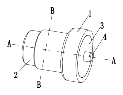
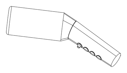
Drawings reproduced from the public patent document for reference.