
Patent CN215294199U
Updated October 26, 2026Manual Quick-Release Connector for Camera Equipment
Swapping a camera between a tripod, a gimbal, or a slider usually means threading screws every time. This quick-release connector replaces that process with a push-and-twist mechanical lock. The system uses a fixed seat and a rotating driving member. Inside the driving member, two communicating grooves guide a limit protrusion on the connecting piece. When you press the connector in, a locking spring rotates the driving member so the protrusion seats under a limiting part in the first groove. To remove it, a button pushes a toggle block, turning the driving member until a positioning piece wedges between the seat and the driver, holding it open while the protrusion moves freely in the second groove. No tools are needed to attach or detach the camera plate.
- China utility model - in force
- No filings outside China
- Camera stands & mounts
- Mechanical push-to-lock release
Splat! What let you down?
🔒
Push-to-lock mechanism
Pressing the connecting piece down rotates the driving member via a spring, catching the limit protrusion in the first groove automatically.
🔘
Button-operated release
A side button pushes a toggle block to rotate the driving member back, wedging the positioning piece to hold the release position open.
⚙️
Internal groove conversion
Communicating first and second grooves inside the driving member guide the protrusion between locked and free states without external levers.
🧩
Split connecting piece
The connecting piece separates into a connecting body and a base, simplifying assembly and maintenance.
Bring this product to market
- ✓ Patent vetted China-only family and legal status checked
- 2 Product brief · now How it works, uses and options written up
- 3 Prototype First samples for buyers to review
- 4 Pilot run Small first batch for launch customers
- 5 Volume production Repeat orders at scale
Buyer interest
– of 100 buyers needed to start prototyping
One click, no sign-up. Each vote is one real visitor, and products with the most interest go to prototyping first.
Build team: no members yet. Need a partner, co-funding or skills to build this? Join and we introduce the team once it forms.
The problem
Photographers and videographers frequently move cameras between tripods, gimbals, sliders, and cages during a single shoot. Traditional mounting relies on threaded screws, which take time to align and tighten, especially when wearing gloves or working in tight spaces. Over repeated use, screw threads wear out, and cross-threading can damage expensive equipment plates. Some existing quick-release systems rely on complex lever mechanisms or proprietary shapes that restrict compatibility across different support brands. Users need a mechanical connection that locks securely by hand, releases predictably, and avoids loose parts that can be dropped on set.
The solution
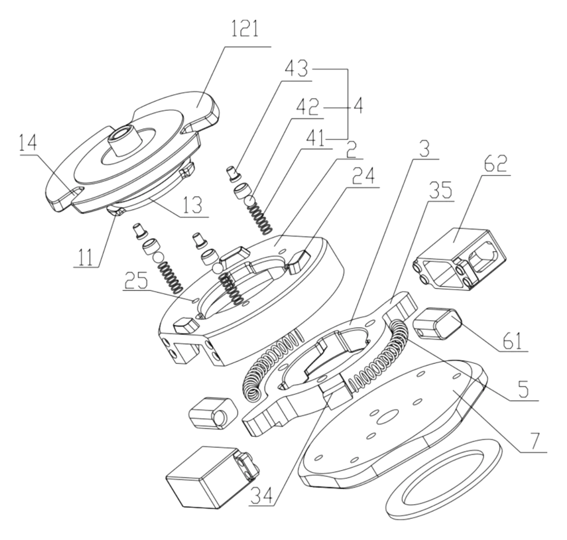
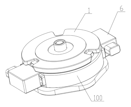
This design solves the issue with a purely mechanical locking device (100) and a detachable connecting piece (1).
- The fixed seat (2) acts as the stationary base, featuring clearance notches (26) on its walls to let the protrusions pass through.
- Inside the seat, a driving member (3) rotates between a locking position and a release position. Its inner wall contains a first groove (31) at the lower end and an axially penetrating second groove (32), which communicate with each other. A limiting part (33) sits at the upper end of the first groove.
- A locking member (4) is placed inside the driving member. It consists of a first elastic piece (41) and a positioning piece (42) resting against its upper end.
- The connecting piece (1) has a limit protrusion (11) on its side wall. When pressed down, the protrusion enters the grooves.
- A locking spring (5) is arranged circumferentially between the driving member and the fixed seat. It stores elastic energy to drive the rotation when the piece is pressed.
- To release, a button device pushes a toggle block (35) on the driving member’s outer wall, rotating it until the positioning piece (42) wedges between the fixed seat and the driving member, keeping the second groove aligned so the piece lifts straight out.
Who it is for
- Camera accessory brands looking to offer a tool-free mounting plate system for their tripods, cages, or rigs without licensing proprietary profiles.
- Gimbal and stabilizer manufacturers needing a fast, repeatable way for operators to balance and swap cameras between handheld and mounted setups.
- Wholesalers and Amazon sellers sourcing reliable mechanical quick-release adapters for photography enthusiasts who want to upgrade from basic screw mounts.
- Broadcast and studio equipment integrators requiring standardized, durable connection points for moving heavy camera bodies between pedestals and jibs safely.
How it works
The main parts
| No. | Part | What it does |
|---|---|---|
| 1 | Connecting piece | Detachable unit carrying the camera; includes connecting body (12) and base (13). |
| 11 | Limit protrusion | Side pin on the base that rides in the grooves to lock or release. |
| 2 | Fixed seat | Stationary housing with sliding grooves (21), through slots, and clearance notches (26). |
| 3 | Driving member | Rotates inside the fixed seat; holds the internal grooves (31, 32) and limiting part (33). |
| 34, 35 | Sliding block, Toggle block | Protrusions on the driving member’s outer wall that ride in the seat’s slots. |
| 4 | Locking member | Contains the first elastic piece (41) and positioning piece (42) to catch the release state. |
| 5 | Locking spring | Circumferential spring pushing the driving member toward the locked position. |
| 6 | Button device | Includes a button, casing, and second elastic piece to push the toggle block for release. |
Operating steps
- Insertion: Align the connecting piece (1) over the fixed seat (2). The limit protrusions (11) pass through the clearance notches (26) and enter the second grooves (32).
- Locking: Press the piece downward. The first elastic piece (41) compresses, and the downward force causes the locking spring (5) to rotate the driving member (3). The limit protrusion slides from the second groove into the first groove (31) and catches under the limiting part (33). The driving member stays in this locking position.
- Releasing: Press the side button. The button pushes the toggle block (35), overcoming the locking spring’s tension and rotating the driving member back. The positioning piece (42) snaps partially between the fixed seat and the driving member, holding the release position open. The limit protrusion is now free in the second groove, allowing the connecting piece to be lifted straight out.
Applications
Tripod and monopod heads
Videographers switching between wide and telephoto lenses often swap entire camera bodies rather than changing glass. This connector allows the operator to press the button, lift the camera, and drop a second one onto the same tripod head instantly. The limit protrusions and matching inclined slopes ensure the plate settles exactly in the center.
Gimbal balancing
Balancing a motorized gimbal requires repeatedly removing and reattaching the camera to adjust the center of gravity. Threaded plates slow this down. With this push-to-lock design, the user drops the connecting piece into the gimbal’s receiver, letting the spring snap it shut, making micro-adjustments much faster.
Studio slider and dolly rigs
Moving a camera from a static tripod to a moving slider involves handling heavy gear over rails. A secure mechanical lock prevents accidental drops if the rig tilts. The circumferential locking spring maintains constant pressure on the driving member, keeping the limit protrusion firmly seated in the first groove even when the slider changes direction abruptly.
Broadcast pedestal mounts
Studio cameras on pneumatic pedestals are moved between sets daily. Operators need a connection that does not rely on fine motor skills to thread a screw while managing cables. The large button device and tactile click of the positioning piece wedging into place provide clear feedback that the mount is either fully locked or fully released.
Where it is less suitable
- Extreme underwater housings: The open clearance notches and sliding grooves could allow water or sand ingress unless heavily sealed in a custom housing design.
- Ultra-micro camera setups: The mechanical components, including the springs and driving member, require a minimum physical footprint, making them too bulky for very small action cameras without scaling down the entire mechanism.
Frequently asked questions
How does the locking mechanism work?
When you press the connecting piece into the fixed seat, the limit protrusions on its side slide down the second grooves. This downward pressure allows the circumferential locking spring to rotate the driving member. As it turns, the protrusions shift into the first grooves and catch under the limiting part, locking the piece in place without needing to twist the camera manually.
How do I release the camera?
Press the button on the side of the housing. The button pushes the toggle block on the driving member’s outer wall, forcing it to rotate back against the spring’s tension. As it reaches the release position, the internal positioning piece wedges itself between the fixed seat and the driving member, holding the grooves open so you can lift the camera straight up.
What is the maximum weight this connector can hold?
The patent describes the mechanical structure but does not specify a maximum payload. The safe working load depends entirely on the materials chosen (e.g., aluminum vs. steel), the thickness of the limit protrusions, and the spring force. These parameters must be set in design and confirmed on prototypes through load testing.
Can the top plate fit standard camera screws?
Yes. The patent mentions a bolt on the upper surface of the connecting plate used for connecting the camera. In production, this is typically machined as a standard 1/4"-20 or 3/8"-16 thread to match common camera bases.
Is the connecting piece one solid part?
The patent describes it as a split design consisting of a connecting body and a connection base joined together. This makes assembly and maintenance easier, as the limit protrusions are formed on the base while the top plate remains on the body.
Does the button stay flush with the housing?
The button device includes a casing and a second elastic piece located between the button and the casing. This spring returns the button to its original position after you press it, keeping the profile clean and preventing accidental snags.
Can this design be made and sold in the US?
This patent was filed only in China and has no US counterpart, meaning this specific document does not restrict manufacturing or sales in the United States. However, the camera quick-release market contains many other active patents globally. We strongly recommend conducting a freedom-to-operate (FTO) review before volume production to ensure your specific implementation does not infringe on other existing US or international patents.
Are you affiliated with the patent owner?
No. IP2M is an independent design and manufacturing service working from the public patent document.
Request a quote
Click Request a Quote below to see our email address - copy it, or open your email app with a ready-made message. Please mention patent CN215294199U in the subject.
Helpful details to include:
- Your company and channel (camera accessory brand, gimbal manufacturer, wholesale distributor, Amazon seller)
- Target payload (approximate camera and lens weight)
- Preferred materials (aluminum alloy, stainless steel, polymer)
- Dimensional requirements (overall diameter, height, top thread size)
- Estimated quantity and target price
- Timeline - when you would like engineering samples and the first shipment
You can also reach us at (332) 203-9997.
Explore this product
Interested in building this?
Tell us your target market, quantity and timeline. We reply with options for prototyping, small-batch runs or volume production.
Send your inquiry to
Please put CN215294199U in the subject line and tell us your company, country, estimated quantity and timeline.
Prefer to talk? Call (332) 203-9997.
More product-ready patents
All Phone & Camera Accessories patents →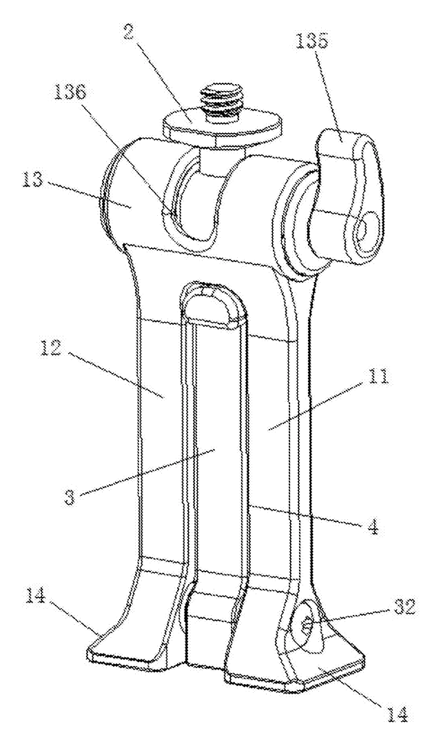
Phone & Camera Accessories
Phone Clip Mount with Fold-Out Stand Leg
Phone clamp adapter with a ball-joint top, a dovetail base for tripod clamps and a fold-out desk leg.
Patent CN207394276U
Phone & Camera Accessories
Extendable Support Leg and Monopod with Single-Knob Locking
Three-section monopod leg locked and released from one top knob via a transmission rod.
Patent CN113090903B
Phone & Camera Accessories
Remote-Controlled Outdoor Photography Tripod with Movable Lens Mount
Motorized tripod with a remote-driven camera seat and a sliding multi-lens mount.
Patent CN118328254B
Hand & Power Tools
Shock-Absorbing Claw Hammer with Interchangeable Strike Faces and Built-In Light
Claw hammer with damping springs, threaded swap faces, magnetic nail slot and LED light.
Patent CN207344510U
School, Office & Art Supplies
Posture-Correcting Retractable Ballpoint Pen with Finger-Guide Elastic Portions
Retractable ballpoint pen: elastic portions on the shell require a correct grip to extend the nib.
Patent CN106739658B
Automotive Parts & Accessories
Adjustable Vehicle Rear Bumper Guard with Telescopic Triangle Frame
Truck rear bumper guard with telescopic rods forming a lifting triangle frame.
Patent CN106347272B
Browse by category
- Apparel & Accessories (22)
- Baby & Kids (16)
- Bags & Luggage (9)
- Bath & Personal Care (16)
- Car Accessories (10)
- Furniture, Bedding & Storage (12)
- Garden & Outdoor (18)
- Health & Wellness (8)
- Home, Kitchen & Cleaning (24)
- Lighting (12)
- Packaging & Containers (6)
- Pet Products (6)
- Phone & Camera Accessories (4)
- Retail Display (13)
- School, Office & Art (19)
- Sports & Recreation (25)
- Tools & Workshop (27)
- Toys & Games (12)
This page is based on the public patent document CN215294199U, assigned to Dongguan Zhipin Creation Digital Technology Co ltd. IP2M is an independent manufacturing service and is not affiliated with, endorsed by or licensed by the patent owner. Images marked as concept renderings are illustrations, not photos of an existing product. Patent status information is provided for reference only and is not legal advice; confirm freedom to operate for your market before production. Full disclaimer.